Wireless Keypad Switches
3 of 4
45 Perseverance Way, Hyannis MA 02601..
009-1758-05 | 200903
| 508.683.2500
1. At the main breaker panel, switch off the breaker that supplies power to the dimmer or switch getting replaced.
2. Unscrew the wall plate and remove it. Verify power is removed using a 120V AC tester.
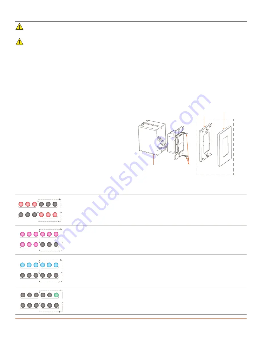
3. Unscrew the two 6-32 flat head screws and pull out the existing electrical switch/dimmer.
4. Disconnect and label each wire removed from the existing switch/dimmer. Labeling the wires ensures they will be installed onto the
new switch/dimmer correctly, mainly if the circuit employs a 3-way configuration.
5. Using the supplied wire nuts or an approved alternative, connect the in-wall wires removed in step 4 to the leads coming from the
new Savant wireless switch/dimmer. See the
sections for more information.
6. Insert the switch/dimmer into the electrical switch box and secure using the 6-32 flat head screws provided. DO NOT use a powered
screwdriver. A powered screwdriver can over tighten the screws.
Electrician Removal/Installation
ELECTRIC SHOCK!
The 120V AC, 60 Hz source power poses an electrical shock hazard that has the potential to cause serious
injury to installers and end users.
IMPORTANT NOTES!
–
A licensed electrician is required to install any Savant wireless lighting devices. Isolate and turn off power at the main breaker
panel before installing any electrical devices.
–
Use #14 AWG or larger solid copper wires (80°C) for the supply, neutral, and ground connections. Strip wires to
⅝
in (16.0 mm).
7. Install the wall plate adapter. When installing, ensure the adapter
completely covers the metal yoke.
8. From the main breaker panel, switch on the breaker that was
switched off in step 1 above.
9. Toggle the power button on the front panel to the ON position.
With power applied, the switch/dimmer will go through a boot
sequence, and both the button and dimming array LEDs on the
front panel will cycle red, green, blue, then white.
10. After the boot sequence completes, the LEDs on the dimming
array will blink red in an alternating pattern, which indicates the
switch is in a state where an IP Address is currently not assigned.
NOTE:
Provisioning will be accomplished later in the process.
11. Press the buttons on the front panel and verify the load reacts
appropriately.
.5s
.5s
Repeat
Three dimming LEDs alternate red left to right.
The keypad is not communicating with the local wireless network and needs to be provisioned. After
a short time (up to one minute), the blinking stops. To check the status of the keypad after the LED’s
stop blinking, press any button on the keypad and the LEDs will begin flashing again to indicate the
state of the keypad.
.5s
.5s
Repeat
Three dimming LEDs on left are solid magenta and three dimming LEDs on the right blink magenta.
The keypad is connected to the local network (IP Address assigned) but not bound to the
configuration running on the Host.
.5s
.5s
Repeat
All Dimming LEDs blink.
Indicates the type of load connected is not supported. Try toggling the service switch or pressing
and releasing the reset button on the front panel. This will reboot and recalibrate the keypad to the
load connected to its output.
NOTE
: Once the keypad connects to a Savant system the color may change but the sequencing
remains the same.
.5s
.5s
Repeat
Rightmost dimming LED blinks green.
Boot loader mode. The keypad is ready/receiving an update.
LED Sequencing
Wall Plate
Adapter
Wall Plate
Electrical
Switch Box
Mounting
Screws
Wall Plate and Adapter
sold separately
12. Install the wall plate once all steps are complete.
13. Once installed, if the keypad is not already provisioned to the local network, provisioning information
is available in the
Wireless Keypad Provisioning Guide
available on the


