Wireless Keypad Switches | 009-1758-05
2 of 4
45 Perseverance Way, Hyannis MA 02601.
Copyright ©2020 Savant Systems, Inc. | 200903
| 508.683.2500
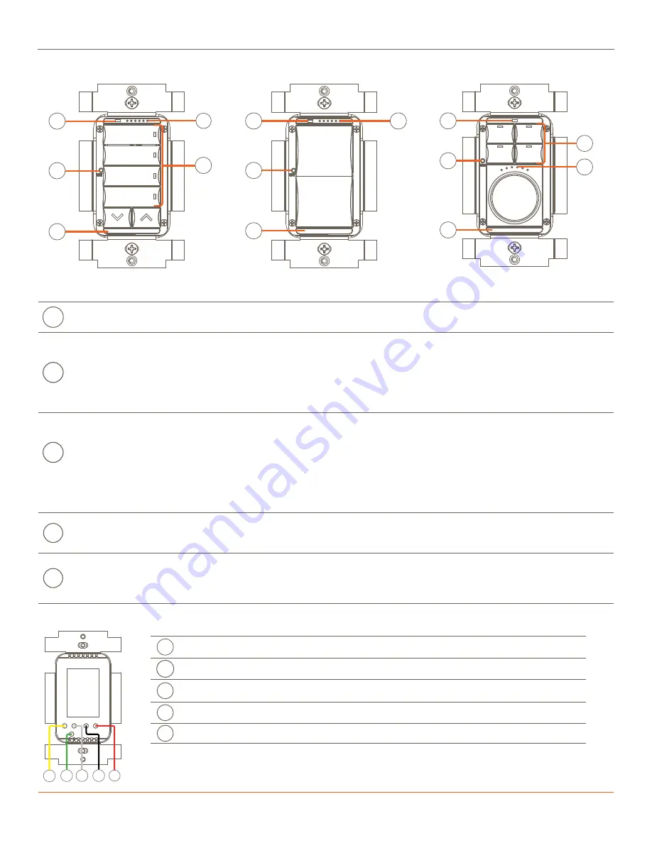
Hardware Overview
Front Panel
Rear Panel
A
Ambient Light Sensor
- Detects the ambient light level in the room and adjusts the brightness of both the button and dimming
LEDs. The ambient light sensor can be enabled or disabled using the Lighting Manager in Blueprint®.
B
Indicator LED’s
- The six status LED’s on the front panel can indicate the following:
–
The amount of power applied to the load. The LED’s light from left to right as the power is increased and switch off from
right to left as the power is decreases.
–
The amount of power applied to the load for any scenes created in Blueprint or the Pro App.
–
The status of the keypad during the setup and provisioning process. See the
C
Reset Button (Press and hold)
- Press and hold the reset button for 5 seconds to clear the network settings then release. Once
released, the switch reboots. During the reboot, the LEDs cycle through a sequence of colors (red > green > blue > white), and
when complete, the LED array on the front panel begins blinking in an alternating pattern. This pattern indicates the switch
is not communicating with a network and needs to be provisioned. For more information on LED patterns, refer to the
section.
Reset Button (Press and release)
- Determines the type of load connected to the keypad’s output wire and calibrates itself
to function with that load. Press and release the reset button to fix issues such as flickering or a load that isn’t performing
optimally.
D
Button LED
- When provisioned to a network, but not configured or bound to a Savant system, the button LED’s track the state
of the output load wire (red wire). When configured and bound to a Savant system, the state of the button LED is defined by
the selection made in the LED Behavior field of the Lighting/Keypad Manager in Blueprint.
E
Service Switch
- Toggle to disconnect or apply power to the load (red wire). When changing a load connected to the switch,
Savant recommends toggling the service switch off, replacing the load, and then toggling the service switch back on. Doing
this calibrates the switch to the new load. If the keypad gets into an unrecognizable state, Savant recommends toggling the
service switch so the keypad can reboot and recalibrate.
A
Yellow
Traveler - Wire to one or more Auxiliary Controls for multi-location control.
B
Green
Ground - Wire to Gnd.
C
White
Neutral - Return path for voltage.
D
Black
Line - Wire to hot from AC power source.
E
Red
Load -Wire to the load.
WPB-xxS106, WIB-xxS106
WPS-xxS102, WIS-xxS102
WPK-xxS105, WIK-xxS105
Wires are all a five inch #16 AWG stranded wire.
B
A
E
D
C
A
B
C
E
A
B
C
D
E
A
B
C
D
E


