background image

4

M-1504 Owner’s Manual

Part No. 001051, 02-m10-2018

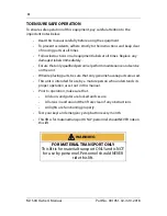
TO ENSURE SAFE OPERATION

To ensure safe operation of this equipment, pay careful attention to the 
important notes below.

Read this manual carefully before using the equipment.

To prevent accidents, adhere strictly to the instructions and keep clear 
of moving parts at all times.

Follow instructions on all equipment labels at all times. Replace any 
damaged labels immediately.

Ensure that only qualified personnel perform maintenance and service 
on the unit.

When replacing parts, be sure that only genuine Savaria parts are used.

This unit is intended for use by a mature person who understands its 
proper operation as set out in this manual.

Prior to operation, make sure that:

All doors and gates are locked and secure.

All areas in and around the lift are clear of any obstructions.

All lights are functioning properly.

Test your keys and emergency stop button every month.

This lift is for material transport ONLY; personnel should NEVER ride on 
this lift.

FOR MATERIAL TRANSPORT ONLY

This lift is for material transport ONLY and is NOT 

for use by personnel. Personnel should NEVER 

ride this lift.

WARNING

Summary of Contents for M-1504

Page 1: ...OWNER S MANUAL To Be Retained by Owner After Installation by Authorized Savaria Dealer Part No 001051 02 m10 2018 M 1504 Material Lift ...

Page 2: ...ore frequently where usage environment or local jurisdiction requires As the Owner you are responsible for ensuring that regular service and inspections occur in a timely manner Refer to this manual for specifications operating instructions and maintenance of the M 1504 Material Lift Upon completion of installation the dealer must provide you with the following information and ensure it is recorde...

Page 3: ...E OPERATION 4 1 DESCRIPTION 5 2 GENERAL SPECIFICATIONS 6 3 OPERATION 8 4 SAFETY FEATURES 10 Optional Scissor Gate 10 Door Lock 11 Safety Brake 12 Manual Lowering and Battery Lowering System 13 5 MAINTENANCE 14 Maintenance Schedule 15 Maintenance Record 16 Operator Troubleshooting 17 ...

Page 4: ...tenance and service on the unit When replacing parts be sure that only genuine Savaria parts are used This unit is intended for use by a mature person who understands its proper operation as set out in this manual Prior to operation make sure that All doors and gates are locked and secure All areas in and around the lift are clear of any obstructions All lights are functioning properly Test your k...

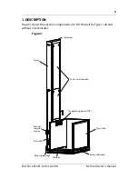
Page 5: ...RIPTION Figure 1 shows the exterior components of a M 1504 with a Type 1 cab and without an enclosure Figure 1 Tower service panels Type 1 cab Platform Car operating panel COP Manual lowering device Safety underpan Tower cap Tower Pit swtich Base support legs ...

Page 6: ...067 mm x 1524 mm Cab walls height Standard 60 1524 mm Optional 80 2031 mm Cab access Enter exit same side platform Type 1L and 1R Front rear access platform Type 2 90 degree access platform Type 3 and 4 Power supply 120 VAC 20 A 60 Hz single phase Control system Electronic free relay logic controller Motor drive 2 1 chain hydraulic 3 HP gear type motor for 110V Tower Modular 8 ft 2 4 m base guide ...

Page 7: ...tomatic battery recharging system 115 VAC Remote manual lowering device Low voltage controls Limit switches Stainless steel checkered platform surface No machine room required Emergency stop button Safety features Bottom and top landing door Door lock Safety brake Emergency stop buttons Manual lowering and battery lowering system Options Fire rated flush mounted landing entrances Custom color Fixe...

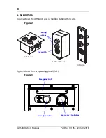
Page 8: ... OPERATION Figure 2 shows the different types of landing stations hall calls Figure 2 Figure 3 shows the car operating panel COP Figure 3 Surface Mount Flush Mount In Frame Key switch Landing buttons Emergency Stop Button Door Open Button Emergency Light ...

Page 9: ...ill not move if one of the doors is open 3 When the lift reaches the landing the door will unlock automatically 4 To prevent unauthorized use of the lift take the key out when the unit is not in operation If you are inside the lift placing a load on the platform and the door closes press the Door Open button to open the door There is also an Emergency Stop button on the COP that when presssdwillst...

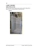
Page 10: ... s Manual Part No 001051 02 m10 2018 4 SAFETY FEATURES Optional Scissor Gate The scissor gate shown in Figure 4 prevents the load from falling off the platform This is an optional feature if required by code Figure 4 ...

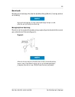
Page 11: ...kept in a safe place for use by trained personnel only Emergency Door Opening The door can be opened manually using a special key inserted into the round pin on the front of the lock Figure 5 Figure 5 After use of any emergency function access key or manual lowering device ensure that all doors gates are secure and locked While the emergency function is in use DO NOT leave the area unattended NOTE...

Page 12: ...tension keeps the brake mechanism up Figure 6 so that the brake s cam doesn t interfere with the tower track If a chain failure occurs the brake mechanism comes down Figure 6 and the brake cam stops the platform Figure 6 Safety brake in operating position Safety brake in down position Safety brake mechanism Brake cam Safety brake mechanism Tower track Right roller guide shoe ...

Page 13: ... lift to the lower level For units with a 120 VAC pump the manual lowering box Figure 7 is located on the side of the M 1504 When you pull on the steel cable located inside the manual lowering box the platform descends to ground level Figure 7 This mechanism is for emergency use only After use of any emergency function access key or manual lowering device ensure that all doors gates are secure and...

Page 14: ...t be performed by a Qualified Technician Contact your Authorized Dealer Units installed in adverse environments will require additional maintenance on a monthly basis Figure 8 Always use the shoring pins when working under the lift For lower travel heights insert the pins into the lower holes at 600 mm NOTE DANGER Shoring pin Shoring pin hole ...

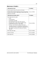
Page 15: ...cy Check the suspension system Chains Connecting links Chain pulleys and shafts Parts holding the chains on the roller supports Chain tensioners on the rail they should be tight Cylinder head cotter pins cracks welds Up relays if you have two up relays solenoids or contactors make sure one of them is not stuck in the activated position Use a multimeter to verify that every N O contact is open when...

Page 16: ...16 M 1504 Owner s Manual Part No 001051 02 m10 2018 Maintenance Record Date Time Reason for Call Comments Dealer ...

Page 17: ...sible solutions If the problem persists contact your Authorized Dealer Potential Problem Possible Solution Lift does not move Check the power supply breaker cord battery etc Check that the key is ON if applicable Check that the doors are closed Check to see if the Emergency Stop is pushed in it should be pulled out for normal operation ...

Page 18: ... Walker Drive Brampton Ontario L6T 5E1 Canada www savaria com For service or questions about this product please contact your installing dealer DEALER NAME _________________________________________________ DEALER PHONE _________________________________________________ Authorized Savaria Dealer ...

Reviews: