Super Vision International
•
8210 Presidents Drive
•
•Orlando, Florida 32809 •
•
407.857.9900
•
Fax 407.857.0050
•
www.svision.com
Super Vision International
•
8210 Presidents Drive
•
•Orlando, Florida 32809 •
•
407.857.9900
•
Fax 407.857.0050
•
www.svision.com
sysTeM TesTing
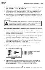
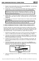
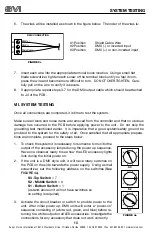
6. The wires will be installed as shown in the figure below. The order of the wires is:
7. Insert each wire into the appropriate terminal block location. Using a small flat
blade screwdriver, tighten each screw of the terminal block until you feel it com-
press the wire and become more difficult to turn. DO NOT OVERTIGHTEN. Care-
fully pull on the wire to verify it is secure.
8. If appropriate, repeat steps 3-7 for the DMX output cable which should be attached
to J4
of the PCB.
VII. SYSTEM TESTING
Once all connections are completed, it is time to test the system.
Make sure all tools and loose items are removed from the controller and that no obvious
damage has occurred to the PCB before applying power to the unit. Do not skip the
grounding test mentioned earlier. It is imperative that a good system/safety ground be
provided to the system for the safety of all. Once satisfied that all appropriate prepara-
tions are complete, proceed to the steps below.
To check the system it is necessary for someone to monitor the
output of the accessory lamps during the power up sequence.
Have one observer ready to see how the LED accessory lights
look during the initial power on.
If the unit is a DMX style unit, it will have rotary switches on
the PCB on the side towards the power supply. Using a small
screwdriver, set the following address on the switches (
See
FIGURE 4a
).
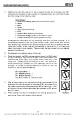
Activate the circuit breaker or switch to provide power to the
unit. After initial power up, DMX units will enter a “power-on”
sequence consisting of (white, red, green, and blue) before re-
turning to a white output on all LED accessories. Investigate the
connections for any accessory that does not work correctly.
1.
2.
3.
DMX CONNECTION
#1
#2
#3
FIGURE 3c
Shield Cable Wire
DMX (-) or inverted input
DMX (+) or non-inverted input
#1 Position
#2 Position
#3 Position
Shield Cable
DMX (-)
DMX (+)
FIGURE 4a
0
5
6
7
8
9
4
3
2
1
0
5
6
7
8
9
4
3
2
1
0
5
6
7
8
9
4
3
2
1
S3
S2
S1
10
S3 -Top Switch
= 7
S2 - Middle Switch
= 0
S1 - Bottom Switch
= 1
(a stand-alone unit will not have switches so
no setting is required)


