background image

Super Vision International 

• 

8210 Presidents Drive 

• 

•Orlando, Florida 32809 •

 407.857.9900 

• 

Fax 407.857.0050 

• 

www.svision.com

sysTeM TesTing (ConT.)

4.  Stand-alone  units  will  come  on  to  one  of  several  modes,  but  will  always  be  “ON” 

when power is provided to the controller.  By toggling power, you can cycle through 
all of the modes in the following order: 

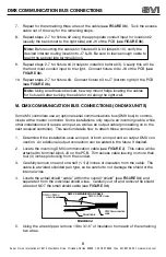
Investigate  the  connections  for  any  accessory  that  does  not  work  correctly.    It  is 
recommended that the colors be cycled until the “white” mode for this test.  Please 
note, that if power remains off for at least nine (9) seconds, the unit will store the last 
mode and a “safety” white mode will be displayed on power up for 12 to 13 seconds 
before the stored mode is recalled.  Please consult the user manual for more detailed 
operation instructions.

5.  Once testing is completed, power off the unit. 
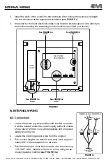
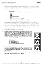
6.  Finally, as desired, the DMX address should be set (for DMX units).  

The top switch (S3) is the “one-hundreds” unit for the address, the 
middle  switch  is  the  “tens”  unit,  and  the  lower  switch  (S1)  is  the 
“ones” unit.  Addresses may be set from 1 to 501.  This unit “uses” 
twelve addresses (so address 501 uses addresses 501 to 512 for 
example).  To set the unit to base address 127 set the S1, S2 & S3 
switches as follows (

See FIGURE 4b

):

7.  After cycling power to the unit again (with the new address on the 

switches), the unit will respond to standard DMX commands (from 
the master controller) at the base address (LED accessory #1 – red), 
up through the next eleven addresses (last address is LED acces-
sory #4 – blue).

8.  When satisfied the unit and installation are working properly, pro-

ceed to the “Close Out” section of this manual. 

FIGURE 4b

0

5

6

7

8

9

4

3

2

1

0

5

6

7

8

9

4

3

2

1

0

5

6

7

8

9

4

3

2

1

S3

S2

S1

S3 -Top Switch

 = 1

S2 - Middle Switch

 = 2

S1 - Bottom Switch

 = 7

Set other address in a similar manner.

Color Modes

Slow color change

 (takes about a minute to cycle)

White
Blue
Green
Aqua

 (Green and Blue)

Pink
Green & Blue fade

 (back and forth)

Fast color change

 (about 15 seconds to cycle)

“Party” mode

 (blinks quickly between colors).


11

Summary of Contents for SAVI-NOTE150

Page 1: ...tallation Manual Super Vision International 8210 Presidents Drive Orlando Florida 32809 407 857 9900 Fax 407 857 0050 www svision com SaVi Note Underwater LED Light SAVI NOTE75 SAVI NOTE150 Model Numb...

Page 2: ...ision International 8210 Presidents Drive Orlando Florida 32809 407 857 9900 Fax 407 857 0050 www svision com Table of Contents Safety Precautions 2 SaVi Note Install Instructions 3 4 M4 Instructions...

Page 3: ...outed by approved methods to conduit fittings on the box For DMX based units do not install data cables in the same conduit as power cables to prevent communication problems Be sure the mounting surfa...

Page 4: ...is not used for swimming and the lens is adequately guarded to prevent any person from contacting it STEP 2 Snake the 4 conductor electric cord through the conduit outlet of the wall fitting into the...

Page 5: ...900 Fax 407 857 0050 www svision com INSTALLATION Instructions 4 STEP 3 Using the lens wrench thread the fixture into the wall fitting until it is snug STEP 4 Wire the fixture to the M4 Controller See...

Page 6: ...5 Installation Manual M4 LED Controller For SaVi Notes and X Stream LED Modules M4 L M4 H M4 L DMX M4 H DMX Model Numbers...

Page 7: ...to complete the mounting of the M4 controller III Conduit and Ground Connections 1 After selecting the desired conduit size or carefully remove the appropriate knock outs in the bottom of the enclosur...

Page 8: ...troller It will be located under the power supply and will consist of one black 120 VAC one white neutral and one green safety ground wire Locate the incoming power wires from the conduit Trim excess...

Page 9: ...is good for this purpose Cut from the desired removal location towards the cut end of the cable to prevent damaging the internal wires Separate the insulation along the cut path and fold it back Usin...

Page 10: ...tions Determine if the installation uses an input or both an input and an output DMX con nection An additional output connection can be added in the future if desired Locate the incoming DMX communica...

Page 11: ...fety of all Once satisfied that all appropriate prepara tions are complete proceed to the steps below To check the system it is necessary for someone to monitor the output of the accessory lamps durin...

Page 12: ...S3 is the one hundreds unit for the address the middle switch is the tens unit and the lower switch S1 is the ones unit Addresses may be set from 1 to 501 This unit uses twelve addresses so address 5...

Page 13: ...facturer will void the entire warranty WARRANTY SERVICE CLAIMS Super Vision must issue a Return Material Authorization RMA number for all requests for warranty review To expedite service please contac...

Reviews: