Super Vision International
•
8210 Presidents Drive
•
•Orlando, Florida 32809 •
•
407.857.9900
•
Fax 407.857.0050
•
www.svision.com
Super Vision International
•
8210 Presidents Drive
•
•Orlando, Florida 32809 •
•
407.857.9900
•
Fax 407.857.0050
•
www.svision.com
inTernal Wiring
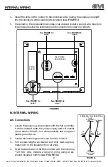
4. Install the ends of the conduit to the enclosure after routing the excess wire length
into the enclosure at the appropriate locations (
see FIGURE 2
)
5. If required by the local electrical codes or as desired, install a ground wire directly to
the enclosure using the external ground connection provided (not shown).
IV. INTERNAL WIRING
A/C Connections
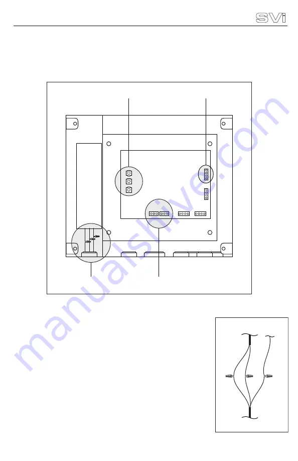
Locate the power pig-tail provided with the M4 controller.
It will be located under the power supply and will consist
of one black (120 VAC), one white (neutral), and one green
(safety ground) wire.
Locate the incoming power wires from the conduit.
Trim excess lengths as desired and strip back approxi-
mately 3/8” of the insulation from all wires.
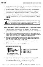
Twist the black wire of the M4 controller with the incoming
“120 VAC” wire. Install a wire nut or crimp using an ap-
proved insulated method (
see FIGURE 3a
).
1.
2.
3.
4.
FIGURE 3
POWER
SUPPLY
PCB - PRINTED
CIRCUIT BOARD
See FIGURE 3a
page 4
See FIGURE 3b
page 5
See FIGURE 4a
page 7
J8
J7
J6
J5
J4
J3
See FIGURE 3c
page 7
POWER PIG-TAIL CONNECTION
FIGURE 3a
To M4
Power Supply To Ground
A/C
Line
(Black)
A/C
Neutral
(White)
A/C
Ground
(Green)
From A/C Input
Conduit
7


