Super Vision International
•
8210 Presidents Drive
•
•Orlando, Florida 32809 •
•
407.857.9900
•
Fax 407.857.0050
•
www.svision.com
Super Vision International
•
8210 Presidents Drive
•
•Orlando, Florida 32809 •
•
407.857.9900
•
Fax 407.857.0050
•
www.svision.com
leD aCCessory ConneCTions
Twist the white wire of the M4 controller with the incoming “neutral” (not the ground)
wire. Secure as in “step (4)” (
see FIGURE 3a
).
Repeat for the green ground wire and the incoming ground wire (
see FIGURE 3a
).
Carefully tuck the wires into the area below the power supply while being careful
that the wires do not lay against the internal components of the power supply.
If possible, verify a grounding path exists between the incoming service ground wire
and the case of the M4 controller. If this is not possible, double check the ground
connection between the crimp and/or wire nut connection and the case of the M4
controller.
V. LED ACCESSORY CONNECTIONS
(Savi notes or X-Stream LED Modules)
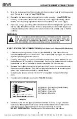
Locate the incoming cable for fixture #1 (
see FIGURE 2
). This cable will be at-
tached to terminal block J5 on the PCB. Trim excess cable leaving no more than six
(6) inches protruding from the conduit.
Carefully remove two (2) inches of insulation from the cable (a box cutter set to pro-
trude less than 1/8” is good for this purpose). Cut from the desired removal location
towards the cut end of the cable to prevent damaging the internal wires.
Separate the insulation along the cut path and fold it back. Using cutters remove
the excess cable insulation. Only the four internal wires should be remaining (red,
green, blue, and a fourth conductor - usually black).
Using the wire stripper, remove 1/8 to 3/16” of insulation from each of the four
wires.
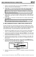
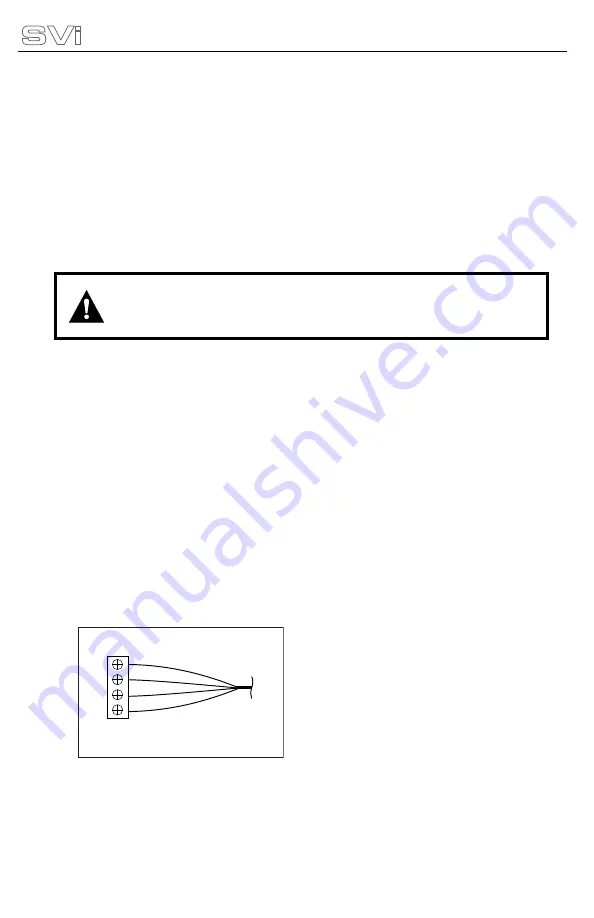
The wires will be installed as shown in
FIGURE 3b
below.
Insert each wire into the appropriate terminal block location. Using a small flat
blade screwdriver, tighten each screw of the terminal block until you feel it com-
press the wire and become difficult to turn (approximately 3.5 in-lbs).
DO NOT OVERTIGHTEN
. Carefully pull on the wire to verify it is secure.
5.
6.
7.
8.
1.
2.
3.
4.
5.
6.
DUE TO ThE DESIRED WATER RESISTAnT SEAL OF ThE EncLOSURE, DO nOT RE-
MOvE Any knOckOUTS UnLESS ThAT hOLE WILL hAvE A cOnDUIT InSTALLED.
IF A knOckOUT IS AccIDEnTALLy REMOvED, STEPS MUST BE TAkEn TO RE-
SEAL ThE OPEnInG OR ThE M4 cOnTROLLER WILL BE DAMAGED.
WARNING
8
LED outputs must be connected as
shown to avoid damage to the circuit
Red
Black
Green
Blue
LED FIXTURE CONNECTION TO TERMINAL BLOCK
#1
#2
#3
#4
FIGURE 3b
#1 Position
- Power Wire (usually Black)
#2 Position
- Red wire
#3 Position
- Green wire
#4 Position
- Blue wire


