background image

1.  To reduce the risk of electric shock, insure 

electricity has been turned off at the 
circuit breaker or fuse box before 
beginning.

2.   All wiring must be in accordance with the 

National Electrical Code and local 
electrical codes. Electrical installation 
should be performed by a qualified 
licensed electrician.

3. 

WARNING:

 To reduce the risk of electrical 

shock and fire, do not use this fan with 
any solid-state fan speed control device.

4. 

WARNING:

 To reduce the risk of fire, 

electric shock, or other personal injury, 
mount fan only on an outlet box or 
supporting system marked acceptable for 
fan support of 35 lbs (15.9 kg) or less and 
use mounting screws provided with the 
outlet box. Most outlet boxes commonly 
used for the support of lighting fixtures 
are not acceptable for fan support and 
may need to be replaced. Consult a 
qualified electrician if in doubt.

5.   The outlet box and support structure must 

be securely mounted and capable of 
reliably supporting a minimum of 50 
pounds. Use only UL Listed outlet boxes 
marked

 "FOR FAN SUPPORT".

6.  The fan must be mounted with a minimum 

of 7 feet clearance from the trailing edge 
of the blades to the floor.

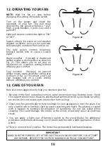
7.   Do not operate reversing switch while fan 

blades are in motion. Fan must be turned 
off and blades stopped before reversing 
blade  direction.

8.   Avoid placing objects in the path of the 

blades.

9.     To avoid personal injury or damage to the 

fan and other items, be cautious when 
working around or cleaning the fan.

10. Do not use water or detergents when 

cleaning the fan or fan blades.  A dry dust 
cloth or lightly dampened cloth will be 
suitable for most cleaning.

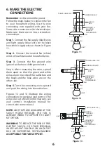
11. After marking electrical connections, 

spliced conductors should be turned 
upward and pushed carefully up into 
outlet box. The wires should be spread 
apart with the grounded conductor and 
the equipment-grounding conductor on 
one side of the outlet box.

12. Electrical diagrams are reference only. 

Light kit that are not packed with the fan 
must be UL Listed and marked suitable 
for use with the model fan you are 
installing. Switches must be UL General 
Use Switches. Refer to the Instructions 
packaged with the light kits and switches 
for proper assembly.

2

3. SAFETY RULES

WARNING

TO REDUCE THE RISK OF FIRE, ELECTRIC 

SHOCK OR PERSONAL INJURY, MOUNT FAN 

TO OUTLET BOX MARKED 

"ACCEPTABLE 

FOR FAN SUPPORT".

WARNING

TO REDUCE THE RISK OF PERSONAL INJURY, 

DO NOT BEND THE BLADE BRACKETS (ALSO 

REFERRED TO AS FLANGES) DURING 

ASSEMBLY OR AFTER INSTALLATION. DO NOT 

INSERT OBJECTS IN THE PATH OF THE BLADES.

ATTENTION


Under the Energy Policy Act of 2005, 

federal regulations require all ceiling fans 

with light kits manufactured or imported 

after January 1, 2009, to limit the total 

wattage consumed by the light kit to 190 

watts. Therefore, this product is equipped 

with a 190W limiting device. If lamping 

exceeds 190 watts, the light kit will shut 

off automatically until the proper wattage 

of bulbs are installed. Reset the light kit by 

turning it off, replacing the bulbs with the 

correct wattage, and then turning the 

light kit back on.

Summary of Contents for 52-CDC-5RV-13

Page 1: ...READ AND SAVE THESE INSTRUCTIONS FAN RATING AC 120V 60Hz UL LISTED MODEL AC 552 MODEL 52 CDC 5RV 13 52 CDC 5RV SN CEILING FAN OWNER S MANUAL ...

Page 2: ...ass shade l Pull chain and fob 2 m Extra plastic plug n Package hardware 1 Mounting hardware screws 2 lock washers 2 star washers 2 wire nuts 3 wood screws 2 washers 2 2 Blade attachment hardware screws 16 fiber washers 16 3 Blade arm hardware screws with lock washers 11 4 Safety cable hardware wood screw lock washer metal washer 5 Balance Kit Philips screw driver Blade screw driver 11 mm wrench S...

Page 3: ...ious when working around or cleaning the fan 10 Do not use water or detergents when cleaning the fan or fan blades A dry dust cloth or lightly dampened cloth will be suitable for most cleaning 11 After marking electrical connections spliced conductors should be turned upward and pushed carefully up into outlet box The wires should be spread apart with the grounded conductor and the equipment groun...

Page 4: ...ort the moving weight of the fan at least 50 lbs Do not use plastic outlet boxes Figures 1 2 and 3 are examples of different ways to mount the outlet box Note You may need a longer downrod to maintain proper blade clearance when installing on a steep sloped ceiling Fig 3 To hang your fan where there is an existing fixture but no ceiling joist you may need an installation hanger bar as shown in Fig...

Page 5: ...th your outlet box Step 3 Remove the hitch pin lock pin and set screws from the top of the motor assembly Step 4 Route wires exiting from the top of the fan motor through the canopy coupling cover and then through the ball downrod Fig 6 Step 5 Align the holes at the bottom of the downrod with the holes in the collar on top of the motor housing Fig 6 Carefully insert the hitch pin through the holes...

Page 6: ...e the ceiling canopy over the collar at the top of the motor Align the mounting holes with the holes in the motor and fasten using the screws and lock washers provided Fig 9 6 Tighten the mounting screws securely WARNING Failure to completely tighten the three screws in step 5 could result in fan loosening and possibly falling 7 Hang the fan on the hook of the hanger bracket Be certain that the ca...

Page 7: ...ecting nuts upward and push the wiring into the outlet box Figures 12 and 13 illustrate the wiring connections for optional wall control The wire color out of wall control may vary see wall control s installation manual for correct wire connections NOTE LIGHT KITS ARE AVAILABLE AT YOU SAVOY HOUSE RETAILER THE FAN IS ALREADY WIRED TO SUPPORT THE LIGHT KIT OPTION WARNING TO REDUCE THE RISK OF FIRE E...

Page 8: ...Secure the canopy to the hanger bracket with the four screws with your fan CLOSE TO CEILING INSTALLATION Remove the fan from the hook on the hanger bracket Secure the canopy to the hanger bracket as shown in Figure 15 with four screws included with your fan Figure 14 Figure 15 Outlet box Hanger bracket Screws Outlet box Hanger bracket Ceiling canopy Screws Ceiling canopy ...

Page 9: ...or using the screws supplied Fig 16 Figure 17 Figure 16 9 INSTALLATING THE MOUNTING PLATE Step 1 Remove the 1 of 3 screws from the mounting ring and loosen the other 2 screws Do not remove Step 2 Place the key holes on the mounting plate over the 2 screws previously loosened from the mounting ring turn mounting plate until it locks in place at the narrow section of the key holes Secure by tighteni...

Page 10: ... 18 Step 3 Install the two 60W candelabra bulbs included Figure 18 Step 4 Raise glass shade up against the light kit and secure it to fan by turning glass clockwise until snug Do not overtighten Restore power and your light kit is ready for operation Figure 18 Figure 18 Figure 19 Mounting plate Wire connection plugs Light kit assembly Bulbs Glass shade Srews 11 FAN WITHOUT LIGHT KIT OPTIONAL 1 Dis...

Page 11: ...thout affecting your comfort Here are some suggestions to help you maintain your fan 1 Because of the fan s natural movement some connections may become loose Check the support connections brackets and blade attachments twice a year Make sure they are secure It is not necessary to remove fan from ceiling 2 Clean your fan periodically to help maintain its new appearance over the years Use only a so...

Page 12: ...t fan wobbling problems are caused when blade levels are unequal Check this level by selecting a point on the ceiling above the tip of one of the blades Measure this distance Rotate the fan until the next blade is positioned for measurement Repeat for each blade The distance deviation should be equal within 1 8 3 Use the enclosed Blade Balancing Kit if the blade wobble is still noticeable 4 If the...

Reviews: