
4
Figure 6
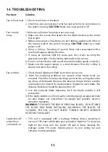
Figure 7
Registration slot
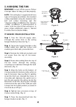
5. HANGING THE FAN
REMEMBER
to turn off the power. Follow
the steps below to hang your fan properly.
NOTE:
This ceiling fan is supplied with two
types of hanging assemblies; the standard
ceiling installation using the downrod with
ball and socket mounting and the
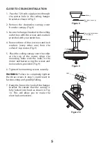
"close-to-ceiling" installation. The "close-to
-ceiling" installation is recommended in
rooms with less than 8-feet ceilings or in
areas where additional space is desired
from the floor to the fan blades.
STANDARD CEILING INSTALLATION
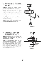
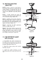
Step 1.
Pass the 120-volt supply wires
through the center hole in the ceiling
hanger bracket as shown in Fig. 5.
Step 2.
Secure the hanger bracket to the
ceiling outlet box with the screws and
washers provided with your outlet box.
Step 3.
Remove the hitch pin, lock pin and
set screws from the top of the motor
assembly.
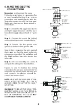
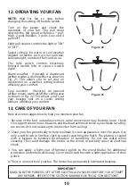
Step 4.
Route wires exiting from the top of
the fan motor through the canopy,
coupling cover and then through the ball/
downrod. (Fig. 6)
Step 5.
Align the holes at the bottom of
the downrod with the holes in the collar on
top of the motor housing (Fig.6). Carefully
insert the hitch pin through the holes in
the collar and downrod. Be careful not to
jam the pin against the wiring inside the
downrod. Insert the locking pin through
the hole near the end of the hitch pin until
it snaps into its locked position, as noted in
the circle inset of Fig. 6.
Step 6.
Tighten two set screws on top of
the fan motor firmly. (Fig. 6)
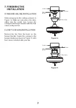
Step 7.
Place the downrod ball into the
hanger bracket socket. (Fig. 7)
Figure 5
Downrod
Set screws
Lock pin
Hitch pin
Tab
Mounting screws
(supplied with
electrical box)
CUL Listed
electrical box
Hanger
bracket
Canopy
Coupling cover


