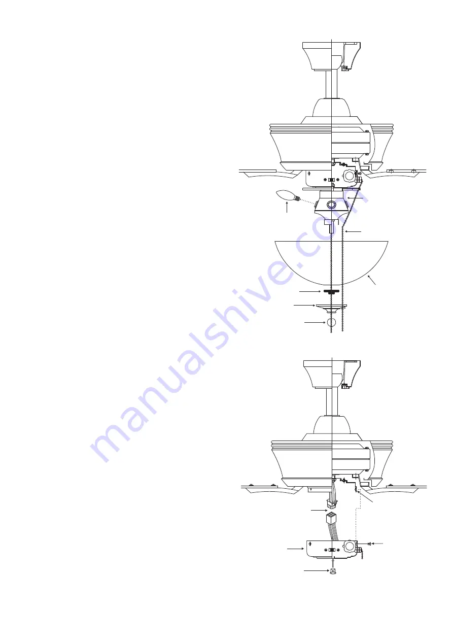
background image

8

Figure 15

Light kit

Bulbs

Pull chains

Glass shade

Decorative nut

Glass cap

Metal nut

13. FAN WITHOUT LIGHT 

KIT 

(OPTIONAL)

1. Disassemble the switch housing from 
the light kit by removing nut and washer 
on the center of switch housing, you can 
keep the light kit for future use.

2. Attach the plastic plug to the switch 
housing. (Fig. 16)

3. While holding the switch housing under 
your fan, snap together the wire 
connection plug. (Fig. 16)

4. Install the switch housing to the 
mounting plate with screws provided. (Fig. 
16 )

Figure 16

Plastic plug

Mounting 
plate

Connection plugs

Switch housing

Screws

12. INSTALLING THE 

LIGHT BULBS & GLASS 
SHADE  

NOTE:

 Before starting installation, discon-

nect the power by turning off the circuit 
breaker or removing the fuse at fuse box. 
Turning power off using the fan switch is 
not sufficient to prevent electric shock.

1. Install 3 x 40W candelabra bulbs 

(included). 

2. Insert the fan pull chain through the 

eyelet in the shade and cap. Also insert 
the light kit pull chain through the 
shade and cap. (Fig. 15)

3.  Remove the metal nut, glass cap and 

decorative nut from the light kit. Place 
glass shade over the light kit stem, 
secure with the metal nut (rubber side 
on the top), glass cap and decorative 
nut. Do not overtighten. (Fig. 15)

Note:

 Make sure to leave enough space 

between the fan pull chain and the bulbs 
so the chain doesn't rub against any of the 
bulbs.

Summary of Contents for 52P-646-5RV-187

Page 1: ...READ AND SAVE THESE INSTRUCTIONS FAN RATING AC 120V 60Hz CUL LISTED MODEL AC 552A MODEL 52P 646 5RV 187 52P 646 5RV 323 CEILING FAN OWNER S MANUAL ...

Page 2: ... Fan motor assembly f Set of blades bracket 5 g Mounting plate h Light kit i Glass shade j 3 x40W candelabra bulbs k Pull chain and fob 2 l Package hardware 1 Mounting hardware screws 2 lock washers 2 star washers 2 wire nuts 3 wood screws 2 washers 2 2 Blade attachment hardware screws 16 fiber washers 16 3 Blade arm hardware screws with lock washers 11 4 Safety cable hardware wood screw lock wash...

Page 3: ...cleaning the fan 10 Do not use water or detergents when cleaning the fan or fan blades A dry dust cloth or lightly dampened cloth will be suitable for most cleaning 11 After marking electrical connections spliced conductors should be turned upward and pushed carefully up into outlet box The wires should be spread apart with the grounded conductor and the equipment grounding conductor on one side o...

Page 4: ...eight of the fan at least 50 lbs Do not use plastic outlet boxes Figures 1 2 and 3 are examples of different ways to mount the outlet box Note You may need a longer downrod to maintain proper blade clearance when installing on a steep sloped ceiling Fig 3 To hang your fan where there is an existing fixture but no ceiling joist you may need an installation hanger bar as shown in Figure 4 Outlet box...

Page 5: ... 5 Step 3 Pass the 120 volt supply wires through the center hole in the ceiling hanger bracket as shown in Fig 6 Step 4 Secure the hanger bracket to the ceiling outlet box with the screws and washers provided with your outlet box Step 5 Remove the hanger pin lock pin and set screws from the top of the motor assembly Step 6 Route wires exiting from the top of the fan motor through the canopy cover ...

Page 6: ...nnect the fan supply black wire and light supply blue wire to the black household supply wire as shown in Fig 10 Step 2 Connect the neutral fan white wire to the white neutral household wire Step 3 Connect the two green fan ground wires located on the mounting plate and motor to the household ground wire Step 4 After connecting the wires spread them apart so that the green and white wires are on o...

Page 7: ...hers 8 FINISHING THE INSTALLATION Step 1 Tuck connections neatly into ceiling outlet box Step 2 Slide the canopy up to hanger bracket and place the key hole on the canopy over the screw on the hanger bracket turn canopy until it locks in place at the narrow section of the key holes Step 3 Align the circular hole on canopy with the remaining hole on the hanger bracket secure by tightening the two s...

Page 8: ...ire connection plug Fig 14 3 Raise the light kit to the mounting plate until the holes in light kit and mounting plate line up Reinsert screws to secure in place Fig 14 Mounting plate Connection plugs Light kit Screws 10 INSTALLATING THE MOUNTING PLATE 1 Remove the 1 of 3 screws from the mounting ring and loosen the other 2 screws Do not remove 2 Place the key holes on the mounting plate over the ...

Page 9: ...ews 12 INSTALLING THE LIGHT BULBS GLASS SHADE NOTE Before starting installation discon nect the power by turning off the circuit breaker or removing the fuse at fuse box Turning power off using the fan switch is not sufficient to prevent electric shock 1 Install 3 x 40W candelabra bulbs included 2 Insert the fan pull chain through the eyelet in the shade and cap Also insert the light kit pull chai...

Page 10: ... warm or cool weather depend on factors such as the room size ceiling height number of fans and so on The slide switch controls directions forward switch left or reverse switch right Warm weather Forward A downward airflow creates a cooling effect as shown in Fig 17 This allows you to set your air conditioner on a warmer setting without affecting your comfort Cool weather Reverse An upward airflow...

Page 11: ...iod Most noise associated with a new fan disappear during this time 5 If using an optional light kit make sure the screws securing the glassware are tight Check that light bulb is also secure 6 Some fan motors are sensitive to signals from solid state variable speed controls If you have installed this type of control choose and install another type of control 7 Make sure the upper canopy is a shor...

Reviews: