background image

READ AND SAVE THESE INSTRUCTIONS

FAN RATING AC 120V. 60Hz

CUL LISTED MODEL : AG-962MC

MODEL: 52-854-5RV-234
                   52-854-5RV-CH
                   52-854-5RV-WH 

CEILING FAN
OWNER'S MANUAL

Summary of Contents for 44-729-5RV-13

Page 1: ...READ AND SAVE THESE INSTRUCTIONS FAN RATING AC 120V 60Hz CUL LISTED MODEL AG 962MC MODEL 52 854 5RV 234 52 854 5RV CH 52 854 5RV WH CEILING FAN OWNER S MANUAL...

Page 2: ...3 l Pull chains and fobs 2 m Package hardware 1 Mounting hardware screws 2 lock washers 2 star washers 2 wire nuts 3 wood screws 2 washers 2 2 Blade attachment hardware screws 16 fiber washers 16 3 B...

Page 3: ...leaning the fan 10 Do not use water or detergents when cleaning the fan or fan blades A dry dust cloth or lightly dampened cloth will be suitable for most cleaning 11 After marking electrical connecti...

Page 4: ...ight of the fan at least 50 lbs Do not use plastic outlet boxes Figures 1 2 and 3 are examples of different ways to mount the outlet box Note You may need a longer downrod to maintain proper blade cle...

Page 5: ...anger bracket as shown in Fig 5 Step 2 Secure the hanger bracket to the ceiling outlet box with the screws and washers provided with your outlet box Step 3 Remove the canopy ring from the canopy Fig 6...

Page 6: ...utlet box securely 5 Remove three of the six screws and lock washers every other one from the collar of top motor Fig 9 6 Place the ceiling canopy over the collar at the top of the motor Align the mou...

Page 7: ...e neutral household wire Step 3 Connect the fan ground wire green to the household ground wire Step 4 After connecting the wires spread them apart so that the green and white wires are on one side of...

Page 8: ...ND WIRING BOX BLK WH BLUE BLK WH FAN LIGHT WH WH BLUE BLK LIGHT FAN 8 FINISHING THE INSTALLATION STANDARD CEILING INSTALLATION Slide canopy up to the ceiling as shown in Figure 15 Make sure you place...

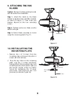
Page 9: ...otor using the screws supplied Fig 17 Figure 17 Figure 18 10 INSTALLATING THE MOUNTING PLATE 1 Remove the 1 of 3 screws from the mounting ring and loosen the other 2 screws Do not remove 2 Place the k...

Page 10: ...g 20 4 Restore power and your light kit is ready for operation 9 Figure 19 Figure 20 11 INSTALLING THE LIGHT KIT NOTE Before starting installation disconnect the power by turning off the circuit break...

Page 11: ...keep the light kit for future use 2 Attach the plastic plug to the switch housing Fig 21 3 Raise and hold the switch housing close to the ceiling fan and connect the connection plugs from the switch h...

Page 12: ...warm or cool weather depend on factors such as the room size ceiling height number of fans and so on The slide switch controls directions forward switch left or reverse switch right Warm weather Forw...

Page 13: ...fan wobbling problems are caused when blade levels are unequal Check this level by selecting a point on the ceiling above the tip of one of the blades Measure this distance Rotate the fan until the n...

Reviews: