background image

READ AND SAVE THESE INSTRUCTIONS

FAN RATING AC 120V. 60Hz

CUL LISTED MODEL : AC-387

MODEL: 52-417-3SV-SN
                  52-417-3WA-13

CEILING FAN

OWNER'S MANUAL

Summary of Contents for 52-417-3SV-SN

Page 1: ...READ AND SAVE THESE INSTRUCTIONS FAN RATING AC 120V 60Hz CUL LISTED MODEL AC 387 MODEL 52 417 3SV SN 52 417 3WA 13 CEILING FAN OWNER S MANUAL...

Page 2: ...ransmitter holder 2 mounting screws l Receiver 6 wire nuts m 100W halogen bulb n Package hardware 1 Mounting hardware screws 2 lock washers 2 star washers 2 wire nuts 3 wood screws 2 washers 2 2 Blade...

Page 3: ...leaning the fan 10 Do not use water or detergents when cleaning the fan or fan blades A dry dust cloth or lightly dampened cloth will be suitable for most cleaning 11 After marking electrical connecti...

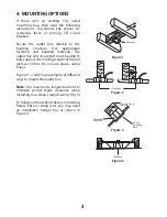
Page 4: ...rt the moving weight of the fan at least 50 lbs Do not use plastic outlet boxes Figures 1 2 and 3 are examples of different ways to mount the outlet box Note You may need a longer downrod to maintain...

Page 5: ...h your outlet box Step 3 Remove the hitch pin lock pin and set screws from the top of the motor assembly Step 4 Route wires exiting from the top of the fan motor through the coupling cover canopy and...

Page 6: ...he ceiling canopy over the collar at the top of the motor Align the mounting holes with the holes in the motor and fasten using the screws and lock washers provided Fig 9 6 Tighten the mounting screws...

Page 7: ...sure the switches on transmitter and receiver are set to the same position any combination of settings will operate the fan as long as the transmitter and receiver are set to the same position Figure...

Page 8: ...the wire connections with the plastic wire nuts provided Step 4 Figure 14 If your outlet box has a ground wire green or bare copper connect it to the fan ground wires otherwise connect the hanging br...

Page 9: ...ws Blade Screws Fiber washers Blades support plates Slot Figure 16 Outlet box Hanger bracket Ceiling canopy Screws 9 ATTACHING THE FAN BLADES Caution Remove the rubber packing mounts and discard befor...

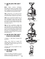
Page 10: ...3 Tuck connections neatly into mounting plate Place the light plate key holes over the 2 screws previously loosened from the mounting ring turn light kit until it locks in place at the narrow section...

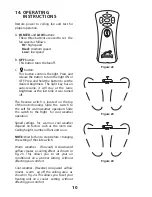
Page 11: ...The Reverse switch is located on the top of the motor housing Slide the switch to the Left for warm weather operation Slide the switch to the Right for cool weather operation Speed settings for warm o...

Page 12: ...ousing CAUTION Make sure main power is off 4 Allow a 24 hour breaking in period Most noise associated with a new fan disappear during this time 5 If using an optional light kit make sure the screws se...

Reviews: