background image

6


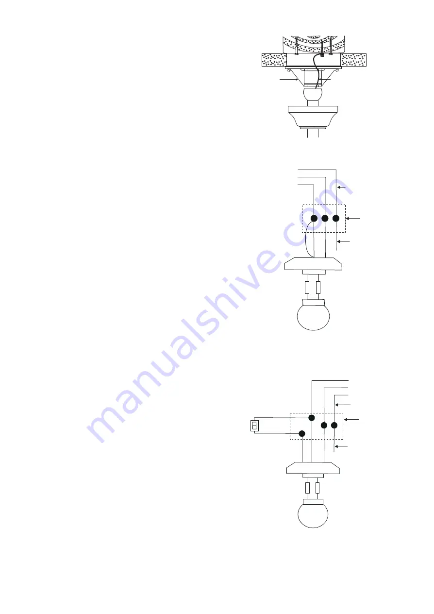
Figure 11

Figure 12

Figure 13

BLK

WH

BLUE 

BLK

WH

GRN

WIRING
BOX

WIRING
BOX

GROUND TO
MOUNTING
BRACKET
OR DOWNROD

GROUND TO
MOUNTING
BRACKET
OR DOWNROD

BLUE

BLK

WH

WH

FAN

LIGHT

POWER LINES 120V

POWER LINES 120V

BLK

WH

BLUE 

BLK

WH

FAN

LIGHT

BLK

BLUE

WH

WH

LIGHT
SWITCH

GREEN GROUND

GREEN GROUND


Hanger bracket

Safety cable

6. INSTALLATION OF 

SAFETY SUPPORT

An additional safety support is provided to 
prevent the fan from falling. Secure the 
safety cable to the ceiling joist with screw 
and washer, as illustrated in Figure 11. 

7. MAKE THE ELECTRIC 

CONNECTIONS

Remember 

 to disconnect the power.

Follow the steps below to connect the fan 
to your household wiring. Use the wire 
connecting nuts supplied with your fan.  
Secure the connectors with electrical tape.  
Make sure there are no loose strands or 
connections.

Step 1. 

Connect the fan supply (black) wire 

and light supply (blue) wire to the black 
household supply wire as shown in Figure 
12.

Step 2.

 Connect the neutral fan (white) 

wire to the white neutral household wire.

Step 3.

 Connect the fan ground wire 

(green) to the household ground wire.

Step 4. After connecting the wires, spread 
them apart so that the green and white 
wires are on one side of the outlet box and 
the black and the blue wires are on the 
other side.

Step 5.

 Turn the connecting nuts upward 

and push the wiring into the outlet box. 

Figures 13 and 14 illustrate the wiring 
connections for optional wall control. (The 
wire color out of wall control may vary, see 
wall control's installation manual for 
correct wire connections.)

Summary of Contents for 52-EUP-5

Page 1: ...READ AND SAVE THESE INSTRUCTIONS FAN RATING AC 120V 60Hz CUL LISTED MODEL AC 552A MODEL 52 EUP 5RV WH 52 EUP 5RV 13 52 EUP 5RV SN CEILING FAN OWNER S MANUAL...

Page 2: ...tra switch housing cover k Pull chains and fobs 2 l Package hardware 1 Mounting hardware screws 2 lock washers 2 star washers 2 wire nuts 3 wood screws 2 washers 2 2 Blade attachment hardware screws 1...

Page 3: ...witch while fan blades are in motion Fan must be turned off and blades stopped before reversing blade direction 8 Avoid placing objects in the path of the blades 9 To avoid personal injury or damage t...

Page 4: ...rt the moving weight of the fan at least 50 lbs Do not use plastic outlet boxes Figures 1 2 and 3 are examples of different ways to mount the outlet box Note You may need a longer downrod to maintain...

Page 5: ...center hole in the ceiling hanger bracket as shown in Fig 5 Step 2 Secure the hanger bracket to the ceiling outlet box with the screws and washers provided with your outlet box Step 3 Remove the hitch...

Page 6: ...ve three of the six screws and lock washers every other one from the collar of top motor Fig 9 5 Place the ceiling canopy over the collar at the top of the motor Align the mounting holes with the hole...

Page 7: ...the wire connecting nuts supplied with your fan Secure the connectors with electrical tape Make sure there are no loose strands or connections Step 1 Connect the fan supply black wire and light supply...

Page 8: ...four screws with your fan CLOSE TO CEILING INSTALLATION Remove the fan from the hook on the hanger bracket Secure the canopy to the hanger bracket as shown in Figure 16 with four screws included with...

Page 9: ...installation disconnect the power by turning off the circuit breaker or removing the fuse at fuse box Step 1 Raise and hold the light kit close to the mounting plate and proceed to do the wire connect...

Page 10: ...rough the eyelet in the shade and cap Fig 19 4 Restore power and your light kit is ready for operation 12 FAN WITHOUT LIGHT KIT Optional 1 Disassemble the light kit assembly from the switch housing yo...

Page 11: ...r warm or cool weather depend on factors such as the room size ceiling height number of fans and so on The slide switch controls directions forward switch down or reverse switch up Warm weather Forwar...

Page 12: ...t connect the fan with a wall mounted variable speed control s 7 Make sure the upper canopy is a short distance from the ceiling It should not touch the ceiling 1 Check that all blade and blade arm sc...

Reviews: