M
J
I
(3)
N
K
L
ON
ON
DI
P
1234
36-329-FD-21
A
B
C
D
(1)
rod
screw
pin
hanger frame
screw
E
G
H
(2)
F
pin
screw
center column
junction box
controller
2
3
4
5
6
(5)
hanger frame
washer
screw
canopy
1
cable
bulb
socket ring
socket
cap
glass shade
glass shade
screw
CEILING FAN PRIMARY FUNCTION
-
IONIZER SECONDARY FUNCTION
READ AND SAVE THESE INSTRUCTIONS
CAUTION:
1. Be certain that no bare wire strands are exposed outside of the wire connectors
2.Disconnect power at main circuit breaker to prevent possible injury from electrical shock.
3.To reduce the risk of fire, electric shock, or personal injury, mount to outlet box marked
(a) and use mounting screws provided with the outlet box.
4. Warning to reduce the risk of electric shock, this fan must be installed with an
isolating wall control/switch
5. Warning - to reduce the risk of fire, electric shock, or personal injury, mount
to outlet box marked (a) acceptable for fan support of 15.9 kg or less,
and use mounting screws provided with the outlet box
ASSEMBLY & INSTALLATION INSTRUCTIONS
Notice:
1.This product contains chemicals known to the state of california to
cause cancer, birth defects and / or other reproductive harm. thoroughly wash
hands after installing, handling, cleaning, or otherwise touching this product.
2.Before using this product and doing maintenance, please read this instruction carefully
and save them for future use.
3.This product is suitable for use with solid-state speed controls
4. The installation is to be in accordance with the national electrical code,
ansi/nfpa 70 and local codes.
5.After being wired, the ungrounded wire and grounded/grounding wire must be separated in
two side of the outlet box
6.The splices, after being made, should be turned upward and pushed carefully up into
the outlet box.
7. The removed controller is suitable for ceiling fan use.
8.This unit is packed completely for ceiling fan use.
9.This unit weighs 17.5kg.
Disconnect the power before installation.
Use and Installation:
Remove all fixture components and the parts bag from the carton.
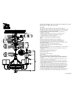
1: Slip the rod (B) with three holes aligning through hanger frame (A), insert the pin (C)
through the hole of the rod (B) and fall into the groove of the half ball tightened with
screw(D).
2: Put the rod (B) into the center column (E), align the side hole and hanger frame hole
with screw (F). Fill the screw hole with Pin (G).
3: Put the glass shade (J) onto socket (I), assemble the glass shade (K) inside the glass
shade (J). Fasten glass shade (K) with socket ring (L) and thread bulb (M) into socket (I).
Screw the cap (N) onto the coupling.
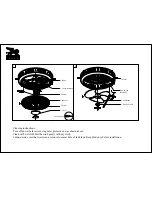
4: Connect main power wire from junction box with the wires of the controller, black
with black, white with white and attach fixture ground wire and ground wire from outlet
box with wire nut. Connect the output wires from controller and fixture wires with wire
connector, colors: black with black, white with white, grey with grey, blue with blue.
5: An additional safety support is provided to prevent the fan from falling. Secure the
safety cable to the ceiling joist with screw and washer,as illustrated in Figure 1.
Thread the screw (4) through washer (3), screw the hanger frame into junction box firmly.
Cover the junction box with canopy (5), fasten the hanger frame (2) with screws (6).
(4)
white wire
black wire
wire connector
ground wire
screw
safety cable
spring washer
flat washer
safety screw
pillar
Figure 1
black black
white white
gray gray
blue blue


