5
Installation
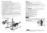
Plumbing
Anti-water hammer device should be provided as required.
Steam Outlet (15mm)
Do not install any valve in steam line. Flow of steam must be unobstructed.
Use 15mm brass pipe or copper tubing from unit to steam head as permitted by codes.
Insulate steam line using pipe insulation rated 120ºC or higher.
Pitch steam line 20mm per meter towards steam head or steam generator to avoid valleys and
trapping of condensate.
NOTE:
Running the steam line down and then up will create a steam trap blocking the
flow of steam.
Steam Head (15mm)
INSTALLER
Because the steam head and direct steam emissions are very hot,
locate the steam head where incidental contact by bather with the steam head or direct
steam emission cannot occur.
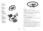
Locate steam head 150-300mm above floor, except for
• Tub/shower enclosures, install 150mm above tub top edge.
• For enclosures with acrylic or other non-heat resistant
flooring install Acrylic Shield.
Install steamhead with steam head facing downward.
Hand tightening is sufficient when teflon or equal pipe
thread sealing compound is used.
IMPORTANT:
To preserve steam head finish, do not
use wrench or other tools to tighten. Use no abrasive
cleansers or chemicals. Use only water with mild soap
and a non-abrasive sponge.
IMPORTANT:
Consult with supplier of acrylic,
fibergl s and other non-heat resistant enclosures
for recommended steamhead location.
Use an Acrylic Shield.
Drain (15mm)
NOTE:
A drain valve is provided to facilitate servicing. Provide a drain line connection from
steambath generator drain valve according to National and local requirements. Check local
plumbing code for receptor, trap and vent requirements. Unit drains by gravity.
Safety Valve (20mm
)
Where permitted by local codes, provide an outlet plumbing connection for safety valve.
1.
2.
3.
4.
5.
6.
7.
1.
2.
3.
4.
1.
2.
3.
Steam Supply Pipe
Steam Head
13mm if not using
Acrylic Shield
19mm if using
Acrylic Shield
Fill in gaps
with silicone or a
sealant of the same
or better quality as
required to seal in
moisture.
Finished interior face
of steam room wall
Make sure to use
Teflon or a sealant
of the same or
better quality
on pipe threads.
Provide a 6mm
minimum clearance if
using an Acrylic Shield
(PN 103412).
See installation
instructions provided
with the Acrylic Shield.
!
WARNING
!
CAUTION
To insure proper and automatic safety valve operation: DO NOT connect
a shut off valve or a plug at safety valve outlet. DO NOT connect a shut off
valve in steam supply pipe.
4
Locating the Steam Generator
1.
2.
3.
4.
5.
6.
7.
8.
9.
10.
11.
12.
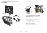
Select a location as near as practical to the steam room. Typical locations include:
closet, vanity cabinet, heated attic or basement.
Locate steambath generator within 7.5 meters of steam room.
NOTE:
The standard length of the cable for connecting the control to the steam generator
is 7.5 meters. The steam generator and control must be located accordingly.
Do not install steambath generator inside steam room.
Do not install steambath generator outdoors or wherever environmental conditions may
affect the safety and/or performance of the generator.
Do not install steambath generator or plumbing lines in unheated attic or any locations
where water could freeze.
Do not install steambath generator near flammable or corrosive materials or chemicals such
as gasoline, paint thinners, or the like. Installation in areas having high concentrations of
chlorine (such as pool equipment room) must be avoided.
Install steambath generator on a solid and level surface. Keyhole slots are provided on for
wall mounting. Insure the steam generator is properly secured and level when mounting
with keyhole slots.
Install steambath generator in an upright position only.
Install anti-water hammer device as necessary.
Provide a minimum of 300mm at both ends and top of the steam generator or as required
for servicing.
Provide unions as required to facilitate installation and disconnection of piping.
IMPORTANT:
Steam line, safety valve, drain valve, plumbing and steamheads become hot
during operation and remain hot after shutdown for a period of time. Provide appropriate
protection, including insulating plumbing lines. Avoid plumbing runs and steamhead
locations that can come in contact with bathers.
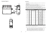
SAWO controls can be located inside the steam room or on the outside of the steam room.
NOTE:
SAWO Generators are CE compliant. Use only SAWO controls.
SAWO in-shower control
Temperature sensor
Control cable
Field installed
power supply
Provide unions as required to facilitate
installation and disconnect of piping
Steam generator
Valve
is shown
open
F
ield
installed
water
supply
pipe
Field
installed
steam
supply
pipe
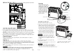
NOTE:
For illustrative purposes only.
Consult with qualified designer, architect or
contractor for steam room construction details.
Steam Head
(shown with optional
acrylic shield)


