7
1. When operated on 220V/1PH, kW output will be 84% of rated kW at 240V/1PH.
2. All three phase heating elements used on 380-430V/3PH products are rated at 415V/3PH.
3. When operated on 380V/3PH, kW output will be 84% of rated kW at 415V/3PH.
4. When operated on 430V/3PH, kW output will be 107% of rated kW at 415V/3PH.
5. Only copper field wiring suitable for 90 degree Centigrade-rated insulation is to be used.
6. For product operating on voltages in excess of 250V, use only 600V rated insulation.
Provide a power supply disconnect within sight of the steam generator or one that is capable of being
locked in the open position as permitted by applicable standards.
Wire sizes in this manual are indicative only, and should be used in conjunction with licensed electricians only.
1.
2.
3.
4.
5.
All electrical wiring to be installed by a qualified licensed electrician in accordance with local
electrical code.
Power Wiring
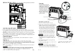
- See page 8 "Field Power Wiring" diagrams.
Check power voltage. Use 220-240V to connect a single phase SAWO steambath generator.
Use 380-430V to connect a 3 phase SAWO steambath generator.
Use minimum 90ºC / 600V rated insulated copper conductors only, sized in accordance with
National Electrical Code and local electrical code for the Amps in Ampere Chart.
Connect suitably sized equipment earth wire to earth terminal provided.
Install a separate circuit breaker between supply and unit. Provide a power supply disconnect
within sight of the steam generator or one that is capable of being locked in the open position.
For single phase units, use two-wire supply source and equipment grounding wire.
Electrical
_____________________________________________________________________
_____________________________________________________________________
_____________________________________________________________________
_____________________________________________________________________
_____________________________________________________________________
_____________________________________________________________________
_____________________________________________________________________
_____________________________________________________________________
____________________________________________________________________
_____________________________________________________________________
_____________________________________________________________________
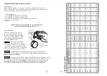
AMPERE CHART
Model No.
kW
Maximum Room
Volume (m³)
Phase
Wire Size
mm²
Current (A)
STS45-1
4.5
3
6.0mm²
4mm²
4mm²
2.5mm²
8.0mm²
2.5mm²
6.0mm²
2.5mm²
2.5mm²
4mm²
20A @ 380V
21A @ 415V
22A @ 430V
16A @ 380V
17A @ 415V
18A @ 430V
12A @ 380V
13A @ 415V
13A @ 430V
10A @ 380V
11A @ 415V
11A @ 430V
8A @ 380V
9A @ 415V
9A @ 430V
35A @ 220V
38A @ 240V
29A @ 220V
32A @ 240V
23A @ 220V
25A @ 240V
6A @ 380V
7A @ 415V
7A @ 430V
18A @ 220V
19A @ 240V
Three
Three
Three
Three
Single
Three
Single
Three
Single
Single
STS45-3
4.5
3
STS60-1
6.0
5
STS60-3
6.0
5
STS75-1
7.5
8
STS75-3
7.5
8
STS90-1
9.0
11
STS90-3
9.0
11
STS120-3
12.0
16
STS150-3
15.0
19
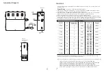
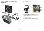
Generator Diagram
6
Water Inlet
Steam
Outlet
Safety
Valve
Manual Drain
Valve
Side view
showing element
access panel
Optional
Automatic Drain


