background image

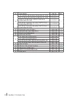
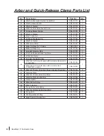
No.

Description

Part No.

Qty.

Miter Gauge Assembly

CNS-07-226

1

21

3/16-24NCx3/8” Pan Head Phillips Screw

CNS-07-227

3

22

Angle Indicator

CNS-07-228

1

23

Mounting Block

CNS-07-229

1

24

Indexing Pin

CNS-07-230

1

25

M5 O-Ring

CNS-07-231

1

26

Miter Gauge Head

CNS-07-232

1

28

8-32x5/8” Pan Head Phillips Screw

CNS-07-234

3

29

8-32 Hex Nut

CNS-07-235

3

30

Miter Gauge Handle

CNS-07-236

1

31

M8x18x3 Washer

CNS-07-237

1

32

Miter Gauge Bar

CNS-07-238

1

33

Gauge Head Mounting Screw

CNS-07-239

1

34

1/4-20x5/16” Flat Head Phillips Screw

CNS-07-240

1

35

Retaining Disc

CNS-07-241

1

Micro-Guard Blade Guard Assembly

TSG-MG

1

36

Top Guard

TSG-MG-001

1

37

Side Guard Front Right

TSG-MG-002

1

38

Side Guard Middle Right

TSG-MG-003

1

39

Side Guard Rear Right

TSG-MG-004

1

40

Side Guard Front Left

TSG-MG-005

1

41

Side Guard Middle Left

TSG-MG-006

1

42

Side Guard Rear Left

TSG-MG-007

1

43

Grooved Clevis Pin (3mm x 8mm)

TSG-MG-008

6

44

3mm E-Style Retaining Ring

TSG-MG-009

6

45

Front Dowel Pin (4mm x 20mm)

TSG-MG-010

1

46

Rear Grooved Pin (4mm x 15mm)

TSG-MG-011

1

47

Top Guard Extension Spring

TSG-MG-012

2

48

M3x0.5x16 Socket Head Cap Screw

TSG-MG-013

1

49

Rear Grooved Pin Spacer

TSG-MG-014

1

50

M3x0.5 Lock Nut

TSG-MG-015

1

51

M3x1.06x8 Pan Head Phillips Screw

TSG-MG-016

1

52

Spreader

TSG-MG-017

1

53

M6x1.0x30 Button Head Socket Screw

TSG-MG-018

1

54

M6x16x1.5 Washer

TSG-MG-019

2

55

Anti-Kickback Pawl Left

TSG-MG-020

1

56

Pawl Bushing

TSG-MG-021

1

57

Anti-Kickback Pawl Right

TSG-MG-022

1

58

M6x1.0 Lock Nut

TSG-MG-023

1

59

M4x25 Spring Pin

TSG-MG-024

1

60

Pawl Spring

TSG-MG-025

1

36-51

Complete Top Guard Assembly

TSG-MG-026

1


SawStop 10” Contractor Saw 

101

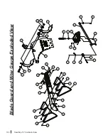
Blade Guard and Miter Gauge Parts List

Summary of Contents for CNS175

Page 1: ...OWNER S MANUAL 10 CONTRACTOR SAW Models CNS175 CNS175 AU SawStop...

Page 2: ...98800 7100483 7197969 7210383 7225712 7228772 7284467 7308843 7350445 7472634 7481140 7525055 7536238 7600455 7610836 7640835 7661343 7681479 7707918 7707920 7788999 7789002 7827890 7832314 7895927 79...

Page 3: ...any injury This manual tells you more about your contractor saw and how to operate and maintain it Please read the manual carefully The manual also includes our warranty and important safety informat...

Page 4: ...Installing the Tilt Handwheel 22 Installing the Motor and Belt Guard 23 Mounting the Extension Wings 24 Mounting the Switch Box 25 Get to Know Your Saw 26 Preparing Your Saw for Use 28 Saw Placement 2...

Page 5: ...able 57 The SawStop Brake Cartridge 58 Changing the Brake Cartridge 59 Installing a Brake Cartridge 62 What to do if the SawStop Safety System Activates 63 Making Adjustments to Your Saw 64 Adjusting...

Page 6: ...ts Lists 86 Stand Assembly Exploded View 86 Stand Assembly Parts List 87 Housing and Table Exploded View 88 Housing and Table Parts List 89 Internal Assembly Exploded View 92 Internal Assembly Parts L...

Page 7: ...or property or incidental consequential contingent or special damages arising from the use of the saw This warranty gives you specific legal rights You may have other rights which vary from state to...

Page 8: ...ing an equipment grounding conductor and a grounding plug The plug must be plugged into a matching outlet that is properly installed and grounded in accordance with all local codes and ordinances Do n...

Page 9: ...ed to a permanent ground such as a properly grounded outlet box 6 A contractor saw that has been re wired for 208 240V power is intended for use on a circuit that has an outlet that looks like the one...

Page 10: ...ting to use the saw for rip cutting without the rip fence could result in serious personal injury 14 Reduce the risk of unintentional starting by making sure the power switch is in the OFF position be...

Page 11: ...OFF and unplug the power cord when you are finished using the saw 25 Turn the main power switch to OFF and unplug the power cord before servicing the saw and when changing components or accessories su...

Page 12: ...aw blade 8 Never try to test fire the brake system 9 Never adjust the position of the brake cartridge while the blade is spinning 10 Do not try to disable the brake system 11 Unplug the saw before cha...

Page 13: ...etection unit detects contact while the blade is spinning including during coast down the fuse is burned by a surge of electric current The spring then pushes an aluminum pawl into the teeth of the sp...

Page 14: ...rted without a blade installed Since the safety system disables the motor if the blade is spaced too far from the brake a missing blade will be detected as a blade to brake spacing error and the motor...

Page 15: ...f the wood Therefore allow wet pressure treated wood to fully dry before cutting Typically the wood will be sufficiently dry if left unstacked in a dry location for 24 hours If you must cut wet pressu...

Page 16: ...e saw components or accessories Read and understand this manual fully before assembling and operating your saw saw with pre installed 10 saw blade zero clearance table insert brake cartridge and brake...

Page 17: ...side of the stand 1 2 3 4 7 F 4 3 2 1 F 8 The front rear and side panels have flanges that overlap to define mounting holes through which you will bolt the saw to the stand There is one hole in each...

Page 18: ...to easily identify the hardware used in each of the following steps the different pieces of hardware are numbered on the hardware pack and in the figures Note If you purchased an optional SawStop Job...

Page 19: ...and four M8 hex nuts to attach the side panel to the front and rear portions Do not fully tighten the nuts Assembling Your Saw 5 Repeat the prior step to attach the remaining side panel marked D to t...

Page 20: ...n tighten all of the nuts in the stand using a 13 mm wrench 7 Attach one long bracket marked F between the legs on the right side of the stand see Fig 7 Make sure the legs are in front of the brackets...

Page 21: ...ollowing the instructions that came with the mobile base Assembling Your Saw Mounting the Saw to the Stand 10 Remove the saw from the box and locate the mounting hardware All of the hardware needed to...

Page 22: ...circui tde frein lorsque lalame tourn e 9 N aju stez jamais lapositi on de lacarto uche de de freina ge 8 N ess ayez jamais d effe ctuer un essai du circui t de lalame 7 Ne passe zpas votre bras par d...

Page 23: ...115 230 Volts 60Hz 15 7 5 Amps 1Phase 1 75 HP 3500 RPM c US 175370 14 Place a level across the table top and adjust the four feet of the stand by turning the lower hex nuts until the table top is lev...

Page 24: ...de the handwheel onto the same shaft Finally thread the elevation lock knob onto the shaft Assembling Your Saw Installing the Tilt Handwheel 16 Open the blade tilt package and slide the handwheel onto...

Page 25: ...les in the rear trunnion see Fig 17 Make sure the pins slide all the way into the holes Use the 3 mm hex key included with hardware pack 2 to tighten the two lock down set screws to hold the motor in...

Page 26: ...op is located in the area with the purple background on hardware pack 2 Position one of the extension wings next to the left side of the cast iron table and align the holes in the side of the wing wit...

Page 27: ...4 11 Mounting the Extension Wings Hardware for Steps 20 21 Lock Washers M8 8 12 Hex Screws M8 x 16 8 13 Hardware Pack 2 Blade Spacing Adjustment Gauge 1 Note You must install a rip fence prior to usi...

Page 28: ...xtension Wings 3 Blade Guard Assembly 4 Standard Table Insert 5 Switch Box 6 Bypass Key 7 Elevation Handwheel 8 Tilt Handwheel 9 Miter Gauge 10 Miter Gauge Slots 11 Spreader Riving Knife Storage Pins...

Page 29: ...r Belt 27 Belt Guard 28 Arbor Block 29 Arbor Nut 30 Arbor Washer 31 Dust Shroud 32 Dust Port 33 Upper Elevation Limit Stop 34 Lower Elevation Limit Stop 35 Brake Positioning Bolt 36 Brake Cartridge 37...

Page 30: ...cement Position the saw on a level surface away from sources of moisture and electrical noise Make sure there is sufficient room to allow free access to all sides of the saw Table Insert Removal and I...

Page 31: ...an standard blades and you could receive a more serious injury Therefore SawStop recommends using blades without depth limiting shoulders The SawStop safety system is designed for use with standard 10...

Page 32: ...ake cartridge and the blade is adjusted by the yellow brake positioning bolt mounted in the top of the arbor block see Fig 32 To access the brake positioning bolt set the tilt angle to 0 and adjust th...

Page 33: ...gauge also contains magnets so it can be attached to the side of the contractor saw housing Alternatively you can place a U S nickel between the brake cartridge and the edge of the blade to set the co...

Page 34: ...The riving knife is an extremely important tool for reducing the potential for kickback when the blade guard cannot be used The riving knife should always be used whenever you need to make rabbet or o...

Page 35: ...ife use the same procedure as installing the guard The clamping force used to hold the spreader and riving knife in place can be increased if the spreader and riving knife are not held securely or dec...

Page 36: ...ust shroud around the blade to provide better dust collection than ordinary contractor saws see Fig 25 Connect a suitable dust collection system to the dust port on the bottom of the dust shroud and a...

Page 37: ...e the contactor box assembly that comes with your saw is only rated for 110 120V power The motor draws 14 amps when it is wired for 110 120V power and 7 amps when it is wired for 208 240V power Do not...

Page 38: ...3 Locate the junction box underneath the motor see Fig 38 on page 35 and remove the cover by loosening the Phillips head screw Inside the junction box are wires connected by two wire nuts One wire nut...

Page 39: ...r wire nut wire nut black white red yellow white black 208 240 V to switch box from switch box Junction Box on Motor to motor wire nut wire nut white black red yellow white green 208 240V Wiring Diagr...

Page 40: ...s the single phase 208 240V power outlet from which you intend to power the saw Connect the white and black wires to the two hot plug terminals Connect the green wire to the ground plug terminal Follo...

Page 41: ...ving the end of the green power cord wire from the ground connection see Fig 42 and 43 With the saw unplugged use a Phillips screwdriver to remove the four screws on the cover of the contactor box and...

Page 42: ...shown in Fig 46 Using a Phillips screwdriver remove the left screw that attaches the bar across the cords entering the contactor box and loosen the right screw Then rotate the bar downwards far enough...

Page 43: ...ot need adjustment If you decide to adjust the blade elevation limit stops see page 64 for instructions CAUTION When adjusting the height or tilt angle of the blade reverse the handwheel slightly to r...

Page 44: ...etes the initialization routine the LEDs will display the READY status display green LED on solid red LED off The saw is now ready for use To start the motor pull the Start Stop paddle out To stop the...

Page 45: ...to place see Fig 50 When the key is removed the main power switch can be turned OFF but it cannot be turned ON Your saw also comes equipped with a thermal overload switch that will cut power to the mo...

Page 46: ...he case of an accident This condition should clear within 15 seconds after the main power switch is turned on If the ambient temperature is very low below about 0 F this code may take longer to clear...

Page 47: ...this error first turn the main power switch to OFF and then make sure the cartridge locking key is correctly installed and turned to ON See page 62 for instructions on how to install and turn on the c...

Page 48: ...ith the safety system active However extremely wet or green wood can interfere with the safety system s ability to detect contact Accordingly the system monitors for wet and green wood and if the wood...

Page 49: ...that is too high to move through the blade guard from entering the guard see Fig 53 The top guard can be placed in an upright position so that you can change the blade without removing the guard Pull...

Page 50: ...rest on the table or insert Make sure the top guard is securely locked in place in the spreader before use Cut the workpiece as described beginning on page 51 The side guards will float on the top of...

Page 51: ...knife as described on page 32 The riving knife should be used whenever the blade guard cannot be used see Fig 59 The only operations where neither the blade guard nor the riving knife can be used are...

Page 52: ...ent should not be necessary If you wish to adjust the index stops see page 74 for instructions For added safety an optional wood face can be mounted to the miter gauge face to provide additional suppo...

Page 53: ...Fig Adjust the miter gauge to the desired miter angle see page 50 Position the workpiece against the miter gauge head and slowly push the miter gauge toward the non spinning blade until the workpiece...

Page 54: ...ional Series is another fence system designed specifically for your saw see Fig 65 It is the best fence system available in the industry The fence is constructed from heavy duty steel tubing for maxim...

Page 55: ...sult Position the workpiece flat on the table and flush against the side of the rip fence Turn on the motor Use both hands to push the workpiece smoothly toward the blade as shown in Fig 66 It is impo...

Page 56: ...h block Continue pushing the workpiece toward the back of the saw until it clears the anti kickback pawls on the spreader Turn off the motor Do not attempt to remove the cut off portion until the blad...

Page 57: ...rom the saw when not in use c While still holding the Bypass Key turned pull the Start Stop paddle out to the ON position The blade will start to spin d Continue to hold the Bypass Key turned for at l...

Page 58: ...esigned specifically for your saw see Fig 71 It attaches to the stand and automatically lifts the saw onto the wheels when you step on a lever When the wheels are down you can roll the saw from one lo...

Page 59: ...back edge of your saw and prevents your workpiece from dropping off the back of your saw during cutting The SawStop Out Feed Table is designed specifically for use with the T GlideTM Fence System Prof...

Page 60: ...h speed and with a large amount of force The brake cartridge must be changed in the event the brake is activated The brake cartridge must also be changed whenever swapping between 10 inch standard bla...

Page 61: ...the Start Stop paddle is pushed in to the OFF position the main power switch is toggled down to the OFF position and the power cord is unplugged The brake cartridge is mounted beneath the table and be...

Page 62: ...ide of the cartridge A cartridge key is used to lock the brake cartridge in place against the cartridge mounting bracket To remove the cartridge first remove the cartridge key by turning it 90 clockwi...

Page 63: ...ce one end of the wrench between the blade and the side of the arbor block and then push the blade a short distance away from the arbor flange see Fig 80 Then place the end of the wrench between the b...

Page 64: ...em that the cartridge is correctly installed and locked in place The system will not allow the saw to start if the switch is not actuated If you attempt to turn on the saw when the key is not in the l...

Page 65: ...rned to SawStop Once the activated cartridge has been removed obtain another brake cartridge that has not been activated and follow the instructions on page 62 to install it If the brake activated due...

Page 66: ...ower the maximum blade elevation adjust the elevation handwheel until the blade elevation is set to the correct maximum height Thread the set screw in clockwise until it is tight To raise the maximum...

Page 67: ...r clockwise with the included 5 mm hex key at least two complete revolutions Then turn the elevation handwheel counter clockwise until the arbor slightly compresses the rubber bumper see Fig 85 The pu...

Page 68: ...mit stop is reached Using a square check to see that the blade is at a 90 angle to the table see Fig 86 If you need to adjust the position of the 0 limit stop follow the instructions below The 0 tilt...

Page 69: ...ustments to Your Saw 45 Tilt Limit Stop To check the position of the 45 limit stop install a 10 inch saw blade on the arbor see page 29 Raise the blade to its full elevation and turn the tilt hand whe...

Page 70: ...lock down lever at the front prevents the insert from rising unexpectedly The insert should slide easily into and out of the table opening but should not be loose in the opening If the insert is too l...

Page 71: ...e the table insert without difficulty The height of the lock down screws can be adjusted using the included 3 mm hex key To set the height of the insert use the included 3 mm hex key to adjust the fro...

Page 72: ...ld be aligned parallel to the blade and positioned inside the kerf of the blade see Fig 93 There should also be a gap of approximately 4 8 mm between the front edge of the spreader or riving knife and...

Page 73: ...blade slide the clamp forward or backward until the spacing is approximately correct When the spreader or riving knife is both aligned and spaced properly tighten the two mounting bolts to hold the qu...

Page 74: ...p and down on the clamp mounting bracket Next adjust the position of the clamp up or down to set the height of the riving knife You can also rotate the clamp forward or backward so that the arc on the...

Page 75: ...to push the clamp open when the handle is raised Therefore you will have to push the handle toward the clamp against the force of the spring When the handle is fully pressed against the clamp an adjus...

Page 76: ...miter gauge in either the left or right miter slot and set a combination square to the desired angle e g 45 0 or 45 Position one leg of the square flush against the blade and rotate the miter gauge h...

Page 77: ...e more slowly thereby resulting in a serious personal injury Elevation and Tilt Mechanisms The elevation and tilt gearing should be kept clean and well lubricated Periodically check the condition of t...

Page 78: ...g green or wet wood 2 Use different wood or cut in Bypass Mode 3 The safety system has detected a system error and is displaying an error code on the LEDs 3 Consult the list of System Status Codes to...

Page 79: ...dge or on the cartridge mounting bracket 2 Try turning and removing the key while pressing upward or downward on the key or cartridge Cannot install the cartridge key 1 The key is not rotated properly...

Page 80: ...miter gauge is not adjusted properly 3 Adjust the miter gauge The material binds when making a rip cut 1 The rip fence is not aligned with the blade 1 Align the fence to the blade 2 The material is w...

Page 81: ...x rip left of blade 161 2 w Contractor Fence Assembly 121 2 w T Glide Fence System Dado diameter 8 requires a separate brake cartridge and table insert Dado max width 13 16 Arbor diameter at blade 5 8...

Page 82: ...llowing U S patents 6813983 6826988 6857345 6877410 6880440 6920814 6945148 6945149 6957601 6994004 6997090 7000514 7024975 7055417 7077039 7098800 7100483 7137326 7171879 7197969 7210383 7225712 7228...

Page 83: ...ame quel que soit le type d op ration 3 Gardez les mains l cart de la lame lorsqu elle tourne 4 Utilisez un poussoir de fin de passe si n cessaire 5 Limitez au maximum le risque de rejet 6 Ne travaill...

Page 84: ...ical pushstick Pushsticks should be constructed from material that is sturdy and electrically non conductive such as scrap wood Pushsticks should always be used when rip cutting pieces narrower than 6...

Page 85: ...ence place it on the saw with piece B flat on the table top and piece A against the left side of the rip fence Position the auxiliary fence so that the front edge of piece B is 1 2 inches back from th...

Page 86: ...pical push block It includes the three pieces shown here labeled A B and C Cut piece A out of 3 4 inch thick hardwood and cut pieces B and C out of 1 2 inch thick plywood Attach piece A to the center...

Page 87: ...d be constructed from good quality wood that is free of knots Use featherboards to help keep the material being cut in contact with the table and to help prevent kickback Do not use featherboards when...

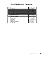
Page 88: ...86 SawStop 10 Contractor Saw Stand Assembly Exploded View 3 8 10 7 1 8 10 4 6 10 8 5 7 10 8 8 10 10 8 10 7 4 10 8 8 12 12 8 12 8 2 8 10 8 10 10 11 9 9 9 1 1 1 5 6 7 7 7 11 10 10 8 8 9 9 9 9 9 13...

Page 89: ...1 4 Stand Side Panel CNS 07 004 2 5 Stand Front Rear Bracket CNS 07 005 2 6 Stand Side Bracket CNS 07 006 2 7 M8x1 25x20 Carriage Bolt CNS 07 007 24 8 M8x16x2 Washer CNS 07 008 40 9 M8 Lock Washer CN...

Page 90: ...s de cabinet lorsque la lame tourne For your own safety read the instruction manual before operating this saw 1 Wear eye protection 2 Use the blade guard and spreader for every operation for which it...

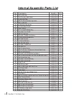
Page 91: ...ing Bracket CNS 07 035 1 23 M6x1 0x8 Button Head Socket Screw CNS 07 036 2 24 Switch Box Cable Grommet CNS 07 037 1 25 M5x0 8 Hex Cap Nut CNS 07 038 1 26 Switch Box Cable Clamp CNS 07 039 1 27 M5x0 8x...

Page 92: ...ms 48 50 54 CNS WA 031 50 M5 External Tooth Lock Washer CNS 09 002 2 51 M5x0 8x8 Button Head Phillips Screw CNS 09 003 2 52 Motor Control Cable Assembly CNS 09 004 1 53 Motor Cable Assembly CNS 09 005...

Page 93: ...SawStop 10 Contractor Saw 91 This page is blank...

Page 94: ...7 16 3 13 15 11 12 14 6 1 8 9 10 8 7 36 37 51 70 72 9 71 71 9 49 39 46 47 48 23 25 38 67 75 5 51 19 22 21 73 74 82 63 77 39 77 7 8 62 69 9 71 79 WARNING Moving belts and parts can pinch cut or crush D...

Page 95: ...yle Retaining Ring CNS 07 069 2 15 1 4 20 NC x 1 4 Set Screw CNS 07 070 2 16 M6x12 Button Head Phillips Shoulder Screw CNS 07 071 1 17 13mm E Style Retaining Ring CNS 07 072 2 18 Motor Mounting Pin CN...

Page 96: ...vation Limit Socket Head Screw CNS 07 117 1 63 M6x1 0x14 Set Screw CNS 07 118 2 64 Elevation Control Shaft Mounting Bracket CNS 07 119 1 65 M6x1 0x20 Socket Head Cap Screw includes M6 washer CNS 07 12...

Page 97: ...SawStop 10 Contractor Saw 95 This page is blank...

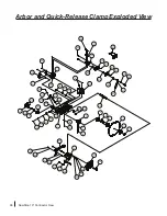
Page 98: ...blade or cartridge changes Use spacing adjustment wrench to set spacing between 1 16 3 32 37 38 28 27 19 20 23 8 9 10 13 4 3 2 15 14 1 16 6 5 7 21 24 22 11 12 69 25 34 35 29 30 31 32 33 54 39 36 26 4...

Page 99: ...153 1 19 Retraction Bracket CNS 07 154 1 20 M8x1 25x16 Button Head Socket Screw CNS 07 155 2 21 Retraction Guide CNS 07 156 1 22 M8x16x2 Washer CNS 07 157 1 23 Retraction Spring CNS 07 158 1 24 M6x33...

Page 100: ...Screw CNS 07 191 2 57 M10x25x3 Washer CNS 07 192 2 58 Spreader Positioning Plate CNS 07 193 1 59 M3x0 5x6 Set Screw for saws with a serial number prior to C154900001 CNS 07 194 1 M4x0 7x6 Set Screw fo...

Page 101: ...SawStop 10 Contractor Saw 99 This page is blank...

Page 102: ...Contractor Saw Blade Guard and Miter Gauge Exploded View 21 22 34 33 26 31 30 28 29 24 25 23 35 32 21 0 15 30 45 0 6 15 30 45 60 36 38 39 40 41 42 43 43 44 44 45 46 47 47 48 49 50 51 37 52 53 54 55 56...

Page 103: ...SG MG 004 1 40 Side Guard Front Left TSG MG 005 1 41 Side Guard Middle Left TSG MG 006 1 42 Side Guard Rear Left TSG MG 007 1 43 Grooved Clevis Pin 3mm x 8mm TSG MG 008 6 44 3mm E Style Retaining Ring...

Page 104: ...the nuts Repeat this process to attach the remaining long bracket between the legs on the left side of the stand 1 2 3 4 7 F 4 3 2 1 F 8 The front rear and side panels have flanges that overlap to de...

Page 105: ...k down lever Phenolic Dado Zero Clearance Table Insert Assembly p n TSI DLD with lock down lever 4 Rip Fences and Extension Tables Contractor Fence Assembly includes fence and rails p n CNS SFA T Glid...

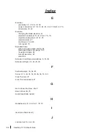
Page 106: ...mperature 44 Anti Kickback Pawl s 47 48 54 71 Arbor block 27 61 63 64 65 diameter 79 nut 13 27 29 runout 79 washer 13 27 29 Assembling Your Saw 16 25 Auxiliary Fence 53 83 B Blade s abrasive blade 12...

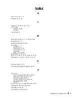
Page 107: ...artridge Cartridge Key 27 44 45 58 60 62 77 Clamping Handle for spreader or riving knife 27 32 33 59 Coast down 11 44 45 Contactor Box Assembly 35 36 38 40 43 76 Contractor Fence Assembly 25 52 79 103...

Page 108: ...ps 41 64 65 miter gears 75 Exploded Views arbor and quick release clamp 96 blade guard and miter gauge 100 housing and table 88 internal assembly 92 stand 86 Extension Cord Recommendations 6 35 38 Ext...

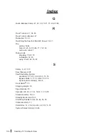
Page 109: ...x stop s 50 74 slot s 26 using 15 26 49 50 Mobile Base 19 56 103 Motor 11 23 24 27 35 36 42 43 45 76 78 Motor Belt 13 15 24 27 36 45 75 77 78 O Out Feed Table 57 103 Overload of the detection system 4...

Page 110: ...nife adjusting 70 72 73 installation 32 33 using 26 27 49 76 78 S Safety 6 9 11 13 Saw Placement 28 SawStop Safety System activation 5 12 13 46 58 63 73 76 Bypass Mode 5 11 13 45 47 55 76 system statu...

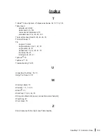
Page 111: ...Thin Kerf blade 71 Tilt angle 41 66 67 angle indicator 26 41 67 78 angle scale 26 41 handwheel 15 22 26 41 79 limit stop 66 67 locking knob 22 41 TopCote 75 TopSaver 75 Troubleshooting 76 78 U Unpack...

Page 112: ...SawStop LLC 11555 SW Myslony Street Tualatin Oregon 97062 USA www sawstop com Main Phone 503 570 3200 Service 503 582 9934 Fax 503 570 3303 Email info sawstop com October 2017...

Reviews: