14
RT-FS/RT-PHFS OWNER’S MANUAL
10
11
12
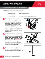
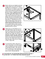
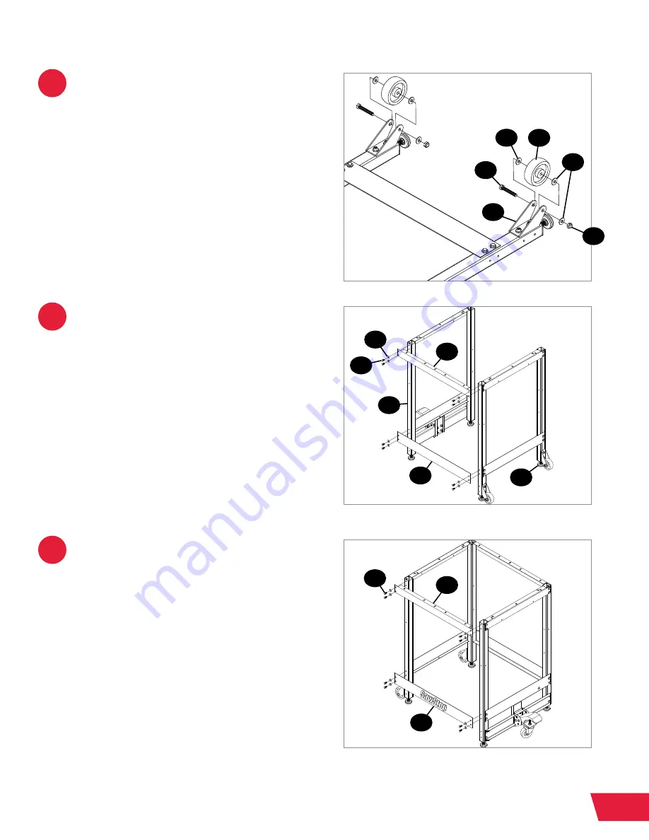
Next, mount the 3” wheels (P) to the
wheel housings (O). Insert a hex head
bolt (Q) through one side of a wheel
housing (O), then through a washer (S),
a 3” wheel (P), a third washer (S), the
other side of the wheel housing (O), and
another washer (S). Secure the bolt with
a lock nut (J). Use two 13mm wrenches
to tighten the nut, but do not over-
tighten the nut, or the wheel will not be
able to rotate. Repeat this process for
the other wheel assembly.
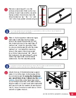
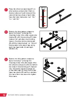
Rotate the stand legs (F) upright so
the leveling feet (M) are on the ground.
Refer to the hole pattern reference
figure from step 7 and align the
mounting holes in an upper front/rear
bracket (D) with the remaining top holes
in two stand legs (F) (marked as holes
“aa”) and align the mounting holes in
a lower front/rear bracket (A) with the
holes in the stand legs (F) marked “cc.”
Mount the brackets (D and A) to the two
stand legs (F) using eight hex head bolts
(V) and eight washers (K).
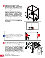
Repeat step 11 with the other upper
front/rear bracket (D) and lower front/
rear bracket (A), then use a 10mm
wrench to tighten all of the hex head
bolts (V) used to assemble the stand.
P
O
Q
S
S
J
D
D
V
V
K
A
F
M
A


