28
RT-FS/RT-PHFS OWNER’S MANUAL
16
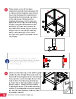
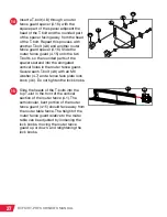
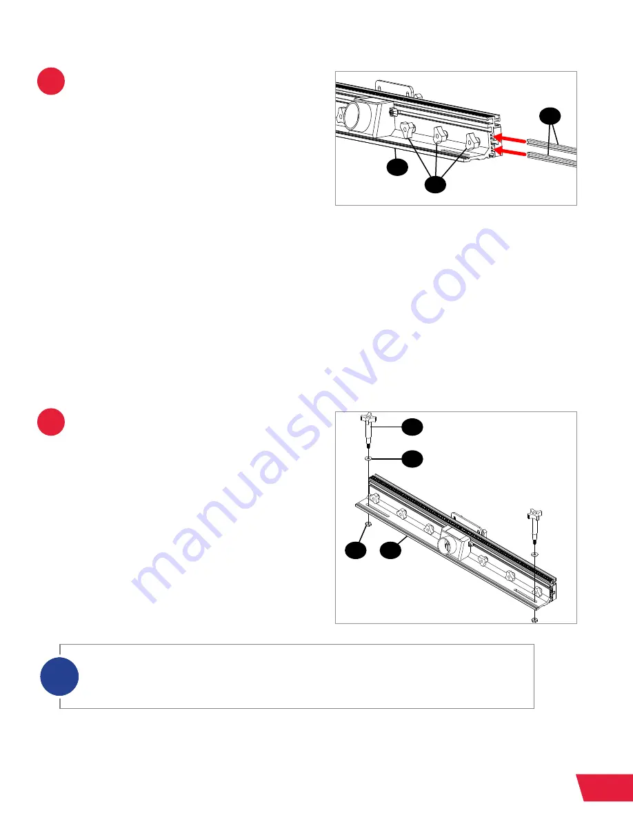
When making jointer cuts, it can be
useful to offset one router fence face
plate (4.14) relative to the other router
fence face plate. Two fence face plate
space bars (4.13) are used to do this,
and they can be installed to offset the
router fence face plates by either 0.7mm
or 1.5mm. It is important to install both
fence face plate space bars facing the
same direction, so they both extend
either 0.7mm or 1.5mm beyond the edge
of the fence. To install the fence face
plate space bars (4.13), loosen the three
lock knobs (4.6) on one side of the back
of the router table fence (4.1), and slide
the two fence face plate space bars onto
the two T-shaped extensions behind the
fence face plate. Then retighten the three
lock knobs to secure the fence face plate
in place.
17
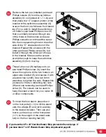
The next step is to attach the router
table fence to the router table. Insert
a fence lock knob (4.2) through an M8
washer (4.3), then through one of the two
elongated holes in the rear of the router
table fence (4.1), and then thread a
19mm wide lock knob nut (4.24) partway
onto the end of the fence lock knob.
Repeat this process with another fence
lock knob, M8 washer, and 19mm wide
lock knob nut.
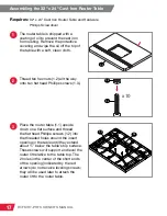
Your 32” Fence Assembly for Router Tables included two sets of lock knob nuts. Use the
smaller, 19mm lock knob nuts (4.24) and discard the larger, 23mm lock knob nuts (4.4). The
23mm lock knob nuts (4.4) are only used when installing the 32” Fence on 30” x 16” Cast Iron
Router Tables.
i
4.13
4.6
4.2
4.3
4.1
4.24
4.1


