19
RT-TGI OWNER’S MANUAL
10
11
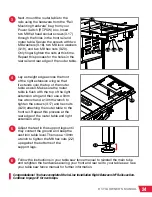
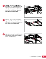
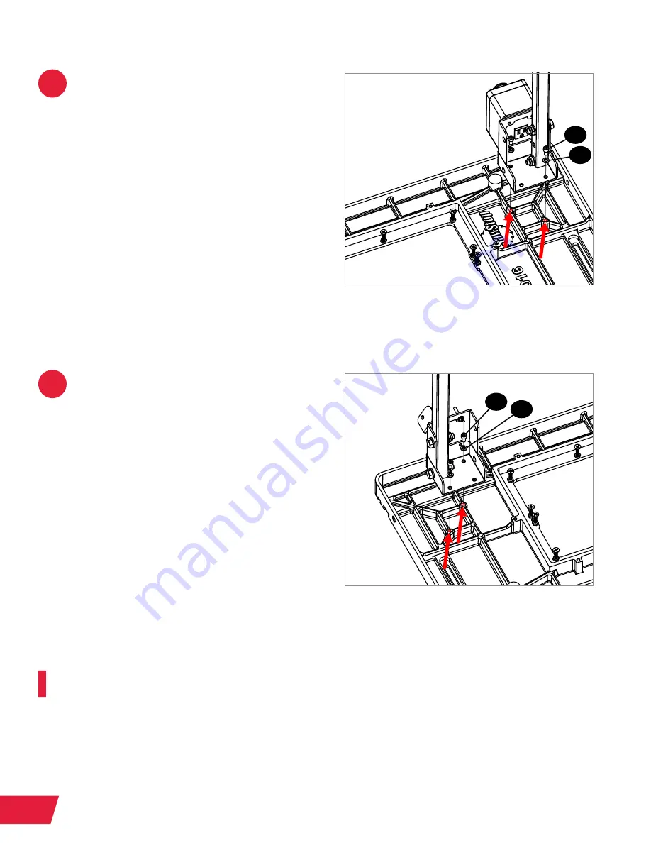
Position one of the leg mounting brackets
(and attached support leg) upside-
down above the router table, with the
front of the leg mounting bracket (either
the switchbox or the handle mounting
bracket) facing towards the front of the
table so it is accessible when the table is
flipped back over and installed on your
Industrial Cabinet Saw. Insert an
M6 socket head cap screw (3.6) through
an M6 lock washer (3.5) and then through
one of the exposed holes in the leg
mounting bracket and router table. Use
a 5mm hex wrench to tighten the screw
(3.6). Repeat this process for the other
hole in the leg mounting bracket that lines
up with a threaded hole in the table.
Repeat step 10 for the other hole in the
leg mounting bracket that lines up with a
threaded hole in the table.
Next, install the router table in one of the three in-line configurations for your Industrial Cabinet
Saw. See pages 1-3 for details regarding the three in-line mounting configurations.
•
For mounting to the left extension wing, proceed to the next page.
•
For mounting near the right extension wing with 36” rails, proceed to page 23.
•
For mounting to the right extension wing with 52” rails and a 36” extension table,
proceed to page 25.
3.6
3.6
3.5
3.5


