23
RT-TGI OWNER’S MANUAL
2
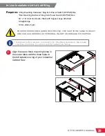
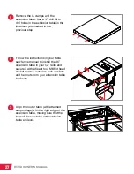
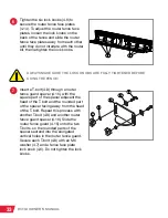
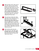
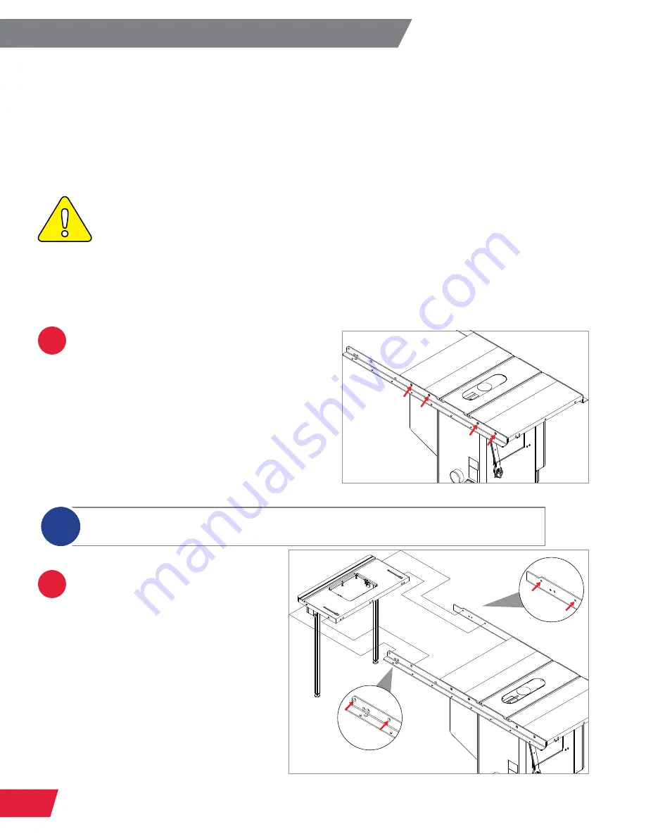
Place the router table between
the front and rear 36” rails, at
the far right end of the rails.
Align the two mounting holes in
each end of the cast iron table
with the corresponding holes in
the rails.
In-Line Installation Right: Between 36" Rails
Requires:
“Rail Mounting Hardware” Bag from Power Switch (RT-PSW) Box
30” x 16” Cast Iron Router Table with Support Legs Attached
Straight
Edge
13mm
Wrench
5mm Hex Wrench
TGI2
Rails
(CBFR Rails are NOT Compatible)
1
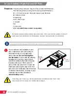
Use a 5mm hex wrench and a 13mm
wrench to loosen the hardware securing
your rear rail to your table saw. See
your table saw fence manual for further
information. (Copies of your manuals can
be downloaded at
www.sawstop.com
.)
SawStop recommends removing the
main tube and loosening the hardware
securing your front rail to your table saw.
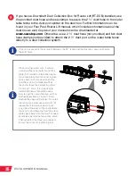
There will be a gap between the right edge of the right cast iron extension wing of your
Industrial Cabinet Saw and the left edge of your router table. Users may choose to build
an intermediate table to install between the cast iron extension wing and router table.
THIS PROCEDURE REQUIRES TWO PEOPLE. THE CAST IRON TABLE IS HEAVY
AND CAN CAUSE SERIOUS PERSONAL INJURY OR DAMAGE IF DROPPED.
The hardware for the next steps can be found in the “Rail Mounting Hardware” bag included
with the Power Switch (RT-PSW) box.
i


