background image

26

RT-TGI OWNER’S MANUAL

2

3

4

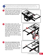
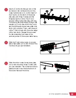
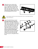
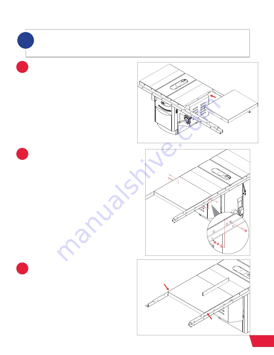
Place the extension table between the 
rails and slide it towards the extension 
wing. Be careful when positioning the 
extension table because it is not yet 
secured to the rails and could fall. 

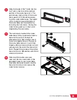
The extension table mounts to the 
rails with bolts that pass through holes 
in the rails and extension table. Take 
two M8 flat head socket screws from 
your extension table hardware, and 
insert one through the hole in the front 
rail closest to the saw and the other 
through the hole in the rear rail closest 
to the saw. Place an M8 washer, an 
M8 lock washer, and an M8 hex nut on 
the threaded end of each bolt, keeping 
them loose. 

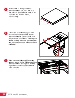
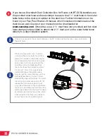
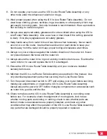
Use a level or straightedge to make 
sure the extension table is flush with 
the right wing of your saw. Then use 
two C-clamps to secure the right end 
of the extension table to the rails. 
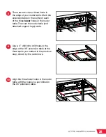
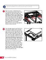
Mark the extension table in the center 
of the three holes in the front rail and 
three in the rear rail. 

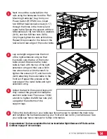
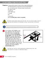
Once the rails are in place, you can mount the extension table to the rails. You will not use all the 
hardware or brackets that are included with your 36” extension table. Follow the instructions in your 
table saw fence manual to install the table. First, drill holes in the sides of the table to mount it to the 
rails. Note that the holes that are closest to the wing are already drilled.

i

Summary of Contents for RT-TGI

Page 1: ...OWNER S MANUAL INDUSTRIAL IN LINE ROUTER TABLE MODEL RT TGI...

Page 2: ...cessory that does not come included with your ICS In Line Router Table Assembly The Four Post Router Lift with Lock and Downdraft Dust Collection Box for Router Lift are also shown installed on the IC...

Page 3: ...CS In Line Router Table Assembly and how to operate and maintain it Please read the manual carefully The manual also includes our warranty and important safety information If you ever have any questio...

Page 4: ...HOW TO GET HELP Missing Parts Have Questions Our technical support team is standing by M F 6 30am 5pm PST to help with whatever you need 503 582 9934 Give us a call at SERVICE SAWSTOP COM Email us at...

Page 5: ...ng Rail Requirements In Line Right of ICS Right Wing In Line Installation Right Between 36 Rails In Line Installation Right Between 52 Rails Assembling the Fence Assembly Reference Warranty Safety War...

Page 6: ...ast Iron Router Table with 32 Fence Assembly can be mounted to your SawStop Industrial Cabinet Saw ICS with T Glide Fence System Industrial Series II TGI2 rails in any of three different configuration...

Page 7: ...table no intermediate table for this configuration is offered by SawStop The gap in the table measures 210mm wide Required Components 30 x 16 Cast Iron Router Table RT C30 Power Switch RT PSW Support...

Page 8: ...irements Required Components 30 x 16 Cast Iron Router Table RT C30 Power Switch RT PSW Support Legs RT ST2 Also included with 36 Extension Table Compatible With T Glide Fence System Industrial Series...

Page 9: ...ling your rails and or extension wings For those steps please refer to your table saw manual and table saw fence manual Download copies of your manuals at www sawstop com For Unassembled Saws If your...

Page 10: ...outer Table Cast Iron Table 30 x 16 Maximum Fence Travel 5 Front T slot to Arbor Center 6 Width of Front T slot at top 3 8 at bottom Width of Rear T slot 1 at top at bottom Rear T slot to Arbor Center...

Page 11: ...PING PURPOSES 30 x 16 Cast Iron Router Table RT C30 30 x 16 Cast Iron Router Table 1 M6 x 1 0 Hex Nut 10 M6 x 1 0 x 40 Flat Head Phillips Screw 10 Mobile Base Cabinet Hold Down Kit for Router Tables 1...

Page 12: ...rt Legs for In Line Router Tables RT ST2 Support Leg 2 M8 x 1 25 Hex Nut 2 Foot 2 A B C A A A C B You will also need the following tools to complete the Support Legs 13mm Wrench See Exploded View 2 on...

Page 13: ...ock Washer 2 M5 x 12 x 1 Washer 2 M5 x 0 8 x 8 Pan Head Phillips Screw 1 Wing Mounting Hardware Pack 1 M8 x 1 25 x 45 Hex Head Bolt 4 M8 x 19 x 2 Washer 8 M8 Lock Washer 4 M8 x 1 25 x 12 Hex Nut 4 Rai...

Page 14: ...Nut 8 Face Plate Space Bar 2 Router Fence Face Plate 2 Router Fence Guard 1 Router Fence Guard Spacer 2 32 Table Rail with Ruler and Lock Knob 2 Rail Mounting Bracket 2 20 x 5 8 Hex Head Bolt 6 M6 x 1...

Page 15: ...ber after the decimal point refers to the part number as indicated by the number in the balloon in the exploded view For example a part referenced as 1 1 would be the part labeled with a 1 balloon in...

Page 16: ...table 1 1 upside down on a flat surface and thread the M6 flat head Phillips screws 1 3 with prethreaded nuts into the threaded holes around the insert opening in the table until they extend about bel...

Page 17: ...shoulder socket screw at the front left of the mobile base in the front support strap as shown by the red arrow in the figure If your saw already has the Industrial Mobile Base installed without the h...

Page 18: ...ox thread the M8 x 1 25 x 18 shoulder socket screw through the larger hole of one of the hold down straps and then back into the same hole in the rear support strap of the mobile base Note the orienta...

Page 19: ...NING 14 RT TGI OWNER S MANUAL 5 6 Fully tighten both screws using a 5mm hex key The mobile base is now ready to place your saw into but first rotate the rear hold down bracket back as far as possible...

Page 20: ...ll with a 1 4 inch hex drive bit to mount the rear hold down bracket to the cabinet There is no need to pre drill a hole for the self tapping screws but be careful not to overtighten the screws or the...

Page 21: ...table support legs are the exact same as the In Line Router Table Support Legs RT ST2 If you are planning on re using the support legs from your extension table refer to your table saw fence manual fo...

Page 22: ...nsert an M10 hex head bolt 3 2 through an M10 washer 3 3 then through one of the exposed mounting holes in the leg mounting bracket 3 7 and support leg through another washer 3 3 and then through an M...

Page 23: ...0 pan head Phillips screw 3 12 through an M5 lock washer 3 9 and an M5 washer 3 10 then through the exposed mounting holes in the handle mounting bracket 3 11 and leg mounting bracket Use a Phillips h...

Page 24: ...table Use a 5mm hex wrench to tighten the screw 3 6 Repeat this process for the other hole in the leg mounting bracket that lines up with a threaded hole in the table Repeat step 10 for the other hol...

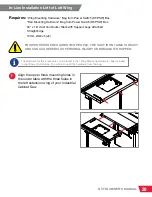
Page 25: ...ight Edge 13mm Wrench x2 1 Align the upper three mounting holes in the router table with the three holes in the left extension wing of your Industrial Cabinet Saw The hardware for this procedure can b...

Page 26: ...p of the router table as well Make sure the router table is flush with the top of the extension wing and then use two 13mm wrenches to tighten the bolt and hex nut closest to the front of the extensio...

Page 27: ...ing SawStop manufactured RT rails No cut templates for rail modification are available from SawStop CORRECT HOLE PATTERNS 36 Industrial Rails Part Number CBFR105 3600 Rails NOT COMPATIBLE 36 Industria...

Page 28: ...ail to your table saw See your table saw fence manual for further information Copies of your manuals can be downloaded at www sawstop com SawStop recommends removing the main tube and loosening the ha...

Page 29: ...the top of the right extension wing and then use a 5mm hex wrench and a 13mm wrench to tighten the screws 3 17 and hex nuts 3 20 attaching the router table to the front rail Repeat this process at the...

Page 30: ...ils are already installed on your saw use a 13mm wrench to remove the main tube set it aside and use a 13mm wrench and a 5mm hex wrench to loosen the hardware securing the rear rail to the saw See you...

Page 31: ...M8 lock washer and an M8 hex nut on the threaded end of each bolt keeping them loose Use a level or straightedge to make sure the extension table is flush with the right wing of your saw Then use two...

Page 32: ...e instructions in your table saw fence manual to install the 36 extension table in your 52 rails and secure it with at least four M8 flat head socket screws washers lock washers and hex nuts from your...

Page 33: ...e three lower holes in the router table Then set the router table and attached support legs aside Use a 3 8 drill bit to drill holes in the edge of the 36 extension table at the three spots you marked...

Page 34: ...l Make sure extension table is flush with the top of the router table and then use two 13mm wrenches to tighten the bolt and hex nut closest to the front of the router table Repeat the process at the...

Page 35: ...nd router table Secure the screws with four M8 washers 3 18 four M8 lock washers 3 19 and four M8 hex nuts 3 20 Use a 5mm hex wrench and a 13mm wrench to tighten the hex nuts Follow the instructions i...

Page 36: ...thread the screw in the hole on the other side of the dust port Slide the two 20 square nuts 4 12 into the lower T slot on the back of the router table fence 4 1 until the dust port is aligned with t...

Page 37: ...bolt and then thread a fence face plate lock knob 4 6 onto the T bolt until the end of the T bolt is flush with the outer edge of the lock knob Repeat this process for the remaining five holes in the...

Page 38: ...e square part of the spacer adjacent the head of the T bolt and the rounded part of the spacer facing away from the head of the T bolt Repeat this process with another T bolt 4 8 and another router fe...

Page 39: ...lock knobs The next step is to attach the router table fence to the router table Insert a fence lock knob 4 2 through an M8 washer 4 3 then through one of the two elongated holes in the rear of the r...

Page 40: ...n the 32 fence and the dust box you can shorten the dust hose i When making jointer cuts it can be useful to offset one router fence face plate 4 14 relative to the other router fence face plate Two f...

Page 41: ...ystem are located or have been used outside of the country where the authorized SawStop distributor from whom the ICS In Line Router Table Assembly system were purchased resides Please contact SawStop...

Page 42: ...nia to cause cancer and birth defects or other reproductive harm In addition some types of dust created by sawing power sanding grinding drilling and other construction activities also contain chemica...

Page 43: ...t pieces between the fence and the router bit 14 Always ensure the router bit is in good working condition before use Examine the router bit prior to use and replace the bit if it is damaged 15 Ensure...

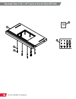
Page 44: ...39 RT TGI OWNER S MANUAL Exploded View 1 30 x 16 Cast Iron Router Table RT C30 RT C30 30 x 16 Cast Iron Table 1 2 3 Industrial In Line Router Table Owner s Manual 4 5...

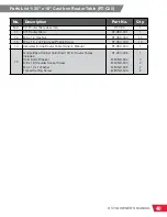
Page 45: ...1 2 M6 x 1 0 Hex Nut RT C30 002 10 1 3 M6 x 1 0 x 40 Flat Head Phillips Screw RT C30 003 10 1 4 Industrial In Line Router Table Owner s Manual RT C30 004 1 1 5 Mobile Base Cabinet Hold Down Kit for Ro...

Page 46: ...41 RT TGI OWNER S MANUAL Exploded View 2 Support Legs for In Line Router Tables RT ST2 ension Legs 1 2 3...

Page 47: ...Parts List 2 Support Legs for In Line Router Tables RT ST2 No Description Part No Qty N A Support Legs for In Line Router Tables RT ST2 1 2 1 Support Leg RT ST2 001 2 2 2 M8 x 1 25 Hex Nut RT ST2 002...

Page 48: ...R S MANUAL Exploded View 3 Power Switch for In Line Router Tables RT PSW RT PSW Power Switch Wing Mounting Hardware Rail Mounting Hardware 3 4 5 6 3 2 7 11 10 9 12 10 9 8 1 3 2 5 6 3 4 13 14 15 16 21...

Page 49: ...RT PSW 008 1 3 9 M5 Lock Washer RT PSW 009 2 3 10 M5 x 12 x 1 Washer RT PSW 010 2 3 11 Handle Mounting Bracket RT PSW 011 1 3 12 M5 x 0 8 x 8 Pan Head Phillips Screw RT PSW 012 1 3 13 M8 x 1 25 x 45 H...

Page 50: ...ly for Router Tables RT F32 2 3 1 4 24 5 14 8 18 19 12 22 17 8 16 15 7 6 21 7 23 20 6 7 10 11 12 9 13 14 3 2 18 18 19 12 22 21 7 23 20 4 for installation on 30 x 16 cast iron router tables 24 for inst...

Page 51: ...1 0 x 35 T Bolt RT F32 008 8 4 9 Fence Ruler RT F32 009 1 4 10 2 Inch Dust Port RT F32 010 1 4 11 20 x Pan Head Phillips Screw RT F32 011 2 4 12 20 Square Nut RT F32 012 8 4 13 Face Plate Spacer Bar R...

Page 52: ...Holds your workpiece safely against the router fence for added stability Easy grip lock knobs Compatible with all SawStop Router Tables and Fences 9 Piece Brass Precision Template Guide Set RT TGS In...

Page 53: ...uter Fence RT FLS Designed to quickly give you accurate repeatable measurements Compatible with all SawStop Router Fences 4 Piece Phenolic Zero Clearance Insert Ring Set for Rout er Lift RT PZR Ultra...

Page 54: ...49 RT TGI OWNER S MANUAL This page is intentionally blank...

Page 55: ...50 RT TGI OWNER S MANUAL This page is intentionally blank...

Page 56: ...M RTR 19 0003 00 February 2018 SawStop LLC 11555 SW Myslony St Tualatin Oregon 97062 USA www sawstop com 503 570 3200 503 582 9934 503 570 3303 info sawstop com Main Phone Service Fax Email...

Reviews: