Sawyer Manufacturing Company
7799 S. Regency Dr., Tulsa, OK 74131 USA
P
918.834.0318
info@sawyermfg.com
P
918.834.2550
sawyermfg.com
V1.2
Installation
DOUBLE CUT TORCH CARRIER
1
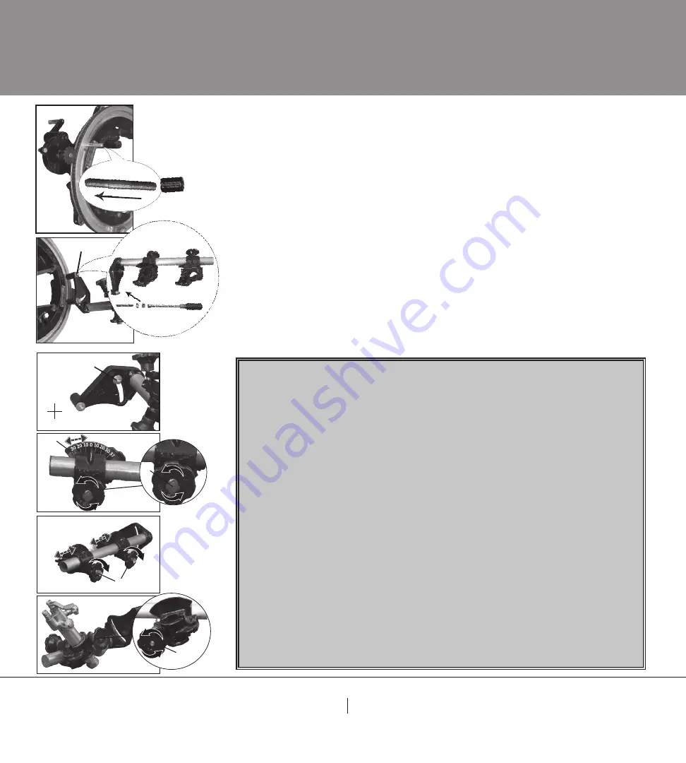
. Mount threaded bolts
(L, Fig. 1)
to Quick Set machine.
A. Place free floating spacer
(K, Fig. 1)
onto threaded bolt.
(L, Fig 1)
Note: Short threads into Quick Set machine not long threads.
2
.
Mount torch arm assembly
(G)
to Quick Set machine.
A. Use 2 washers
(I, Fig. 1)
, & 2 9/16” nuts.
(H, Fig. 1)
Tip: Use 9/16” Wrench.
3
.
Mount hoses to torches.
Note: Oxygen Hoses are green and Fuel Gas Hoses are red.
Note: Fuel Gas Hoses have notches on them and thread counter clockwise.
Tip: It is recommended to use a male-to-male adapter.
Installation
Operation
*Please refer
to the Quick
Set manual for
Operation of
Quick Set*
Torch Arm Setup
1.
Adjust torch arm assembly.
(F, Fig. 2)
A. By loosening the 9/16” nut.
(G, Fig. 2)
Adjust torch arm
assembly
(G, Fig. 2)
to most southern point.
B. Tighten 9/16” nut.
(H, Fig. 2)
2.
Bevel Angle Adjustment.
(Fig. 3)
A. Loosen bevel indicator square nut.
(C, Fig. 3)
B. Adjust bevel indicator
(F)
to desired angle
. (Fig. 3)
C. Tighten bevel indicator square nut.
(C, Fig. 3)
Tip: Use ½” wrench.
3.
Position Adjustment.
(Fig. 4)
A. Loosen position adjustment knob.
(B, Fig. 4)
B. Move assembly to desired position.
C. Tighten position adjustment knob.
(B, Fig. 4)
4.
Install Torch Inside Torch Holder.
A. Loosen torch holder adjustment knob.
(A, Fig. 5)
B. Install torch inside torch holder.
C. Tighten torch holder adjustment knob.
(A, Fig. 5)
*Please refer to the Quick Set
manual for Installation of Quick Set*
J
C
F
B
G
N
S
E
W
A
Fig. 2
Fig. 3
Fig. 1
L
Fig. 2
K
L
Fig. 4
Fig. 5
*Please refer
to the Quick
Set manual for
Operation of
Quick Set*


