background image

Introduction

The EasySplicer incorporates all the best a fixed v-groove splicer can offer.

NOTE: EasySplicer is a high precision instrument and should always be handled with care!

Disclaimer

SB Scandinavia AB reserves the right to modify the product in any way without prior 
customer notification or any other form of notice. 

In no event shall SB Scandinavia AB be liable for any damages of any type, incidental, 
indirect, consequential or other, originating from or relating to this manual or the 
information contained herein. While SB Scandinavia AB tries to make the user manual 
complete and accurate, it may contain mistakes, and the user uses it solely at his or her 
own risk.

Application

Splicing and protection of most common types of SMF and MMF.

Fusion splicer components

The following components are included and standard for splicing in the field:

Item 

Description 

Quantity

EasySplicer 

1

Power supply 

1

3

Fiber cleaver 

1

4

Fiber holders 250µm

1 pair

5

Fiber holders 900µm

1 pair

6

Stripper

1

7

Carrying bag

1

8

Users manual on CD

1

3

Summary of Contents for EasySplicer

Page 1: ...USERS MANUAL EasySplicer 1 ...

Page 2: ...e splicer to power 4 Starting the splicer 4 Fusion splicer menus 4 Main menu 6 Setup menu 7 Fiber type menu 7 Set clock menu 8 Preparing the fiber 9 Protective sleeve 9 Stripping the fiber 9 Cleaning the fiber 10 Cleaving the fiber 11 Splicing 13 Cleaning the v groove of the fusion splicer 16 Oven maintenance 17 Technical data 18 2 ...

Page 3: ...consequential or other originating from or relating to this manual or the information contained herein While SB Scandinavia AB tries to make the user manual complete and accurate it may contain mistakes and the user uses it solely at his or her own risk Application Splicing and protection of most common types of SMF and MMF Fusion splicer components The following components are included and standa...

Page 4: ...asy way Turn on the splicer Select proper splice program Run calibrate process with a piece of fiber Prepare the fibers Splice the fibers Analyze the splice Remove the fiber Protect the splice Connecting the splicer to power Connect the power supply if power is available Or use the internal battery Starting the splicer Start the splicer by pressing the large button until the splicer starts Fusion ...

Page 5: ...tep every splice but when changing environment this calibration will be needed To prepare for this calibration strip and clean a piece of fiber and place it all the way through the v grove and then start the calibration The PWR value will be updated TURN OVEN ON Manually run the oven program Normally when a splice is done next step is to move the fiber with a sleeve to the oven and press the OVEN ...

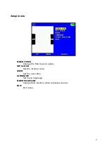
Page 6: ...menu FIBER TYPES Change the fiber type to splice SET CLOCK Set the internal clock OVEN Set the oven time LANGUAGE Set menu language FIBER POSITION Change fiber position when replacing cleaver EXIT Exit menu 6 ...

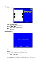
Page 7: ...cing SMF MULTI MODE FIBER Setup splicer for splicing MMF EXIT Exit menu Set clock menu UP Changes selected items up one step DOWN Changes selected items down one step MOVE Steps to next item When Exit item is selected chose Exit button to set the new time 7 ...

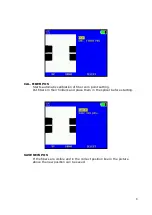
Page 8: ...ibration of fiber zero point setting Put fibers in their holders and place them in the splicer before starting SAVE NEW POS If the fibers are visible and in the correct position like in the picture above the new position can be saved 8 ...

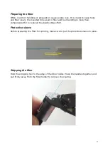
Page 9: ...and tool handling is more than compensated for in reduced troubleshooting effort Protective sleeve Before preparing the fiber for splicing make sure to put the protective sleeve in place Stripping the fiber Hold the stripping tool to the edge of the fiber holder Press the handles together and pull firmly away from the fiber holder to remove the coating 9 ...

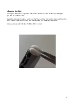
Page 10: ...soaked in alcohol according to picture or a similar tool Press the tweezers together and clean the fiber with by moving the tweezers from the fiber holder towards the end of the fiber Repeat but rotate the tweezers A squeaking sound indicates that the fiber is clean 10 ...

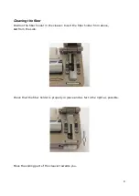
Page 11: ...ion the fiber holder in the cleaver Insert the fiber holder from above not from the side Check that the fiber holder is properly in place and as far to the right as possible Move the sliding part of the cleaver towards you 11 ...

Page 12: ...Close the cleaver lid and push the sliding part away from you Lift the fiber holder up so that it don t get dirty 12 ...

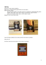
Page 13: ...e and move it passed its intended resting place Fold the fiber holder down until it makes contact with support surface Gently pull the fiber holder back until it snaps in place Repeat for the other fiber holder Lower the fiber pressure foot slowly and lock the fibers in position Close the lid The fiber should now be visible in the monitor like below 13 ...

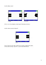
Page 14: ... re do the stripping cleaning and cleaving procedure Are the fibers properly aligned If not make sure the fiber holders are properly snapped into place If this does not help clean the v groove described below 14 VERY BAD GOOD BAD ...

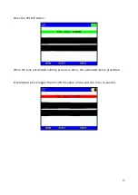
Page 15: ...Press the SPLICE button When the fully automated splicing process is done the estimated loss is presented If estimated loss is bigger than 0 1dB the splice is bad and has to be re spliced 15 ...

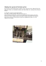
Page 16: ...ry cleaning the surface as follows To clean the v groove proceed as follows Put a fiber in a fiber holder strip clean and cleave it Use this fiber to scratch the v grove at an angle several times back and forth Then put the fiber in place like you would do a splice and check the removed dirt via the camera This procedure should be repeated until there is no dirt visible to the camera 16 ...

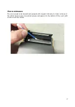
Page 17: ...maintenance The oven needs to be cleaned and greased with regular intervals to make removal of the shrink sleeves easy Use silicon grease and apply it to the bottom of the oven with a cotton bud See below 17 ...

Page 18: ...pical Loss SMF 0 03dB MMF 0 01dB Splice Programs 2 factory defined Display 2 8 Color TFT Power source Battery 7 4V 2200mAh Built in Power supply 100 240V AC 6V DC 1 25A Operating environment Temperature 0 C to 45 C Humidity max 95 RH non condensing Storage environment Temperature 20 C to 60 C Humidity max 98 RH non condensing Heat oven Built in 18 ...

Reviews: