21
84
121
2
|
PCD7.LR-TR4x Wall Modules
INSTALLATION INSTRUCTIONS
|
31-00133
MOUNTING
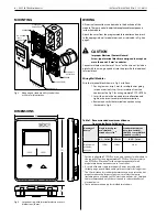
Fig. 3. Mounting on standard utility conduit box
or 60 mm wall outlet box.
Fig. 4. Large housing, with terminal protection covers,
dimensions (in mm)
Table 1. Recommended maximum distance
from controller to Sylk device
Quantity of
device
a
Single twisted pair,
non-shielded,
stranded or solid
b
Standard thermostat
wire, (non-twisted),
shielded or nonshielded,
stranded or solid
c,d
0.3…1 mm
2
0.25 mm
2
0.25…1 mm
2
Up to 4 wall
modules,
any type
150 m
120 m
30 m
a
For the configurable PCD7.LRxx it can only connect 1 wall module to
the controller. For the programmable PCD7.LRxx-P5 please refer to
the PCD7.LRxx-P5 manual for the maximum quantity of wall
modules which can be connected to 1 controller.
b
As a rule of thumb, single twisted pair (2 wires per cable only),
thicker gauge, non-shielded cable yields best results for longer runs.
c
The 30 m distance for standard thermostat wire is conservative, but
meant to reduce the impact of any sources of electrical noise
(including but not limited to VFDs, electronic ballasts, etc). Shielded
cable recommended only if there is a need to reduce the effect of
electrical noise.
d
These distances also apply for shielded twisted pair.
All terminal connections can be made to the backside of the
module. There are no field adjustable/replaceable components
inside the module.
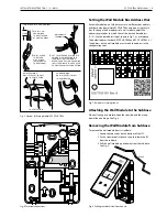
Attach the wires from the programmable controller and network
to the appropriate wall module terminals, as indicated in Fig. 6 on
page 3.
CAUTION
Improper Electrical Contact Hazard.
Screw-type terminal blocks are designed to accept no
more than one 2.5 mm
2
conductor.
Connect multiple wires that are 2.5 mm
2
with a wire nut. Include a
pigtail with this wire group and attach the pigtail to the individual
terminal block.
Wiring Wall Modules
Wire the terminal block shown in Fig. 6 as follows:
1. For single wires, strip 5 mm; for multiple wires going
into one terminal, strip 13 mm insulation from the
conductor. See Fig. 5 for wiring multiple PCD7.LR-TR4x.
2. Insert the wire in the required terminal location and
tighten the screw to complete the termination.
3. Review and verify the terminal connection wiring
illustrated in Fig. 6.
DIMENSIONS
WIRING
STANDARD UTILITY
CONDUIT BOX
SUBBASE
NO. 6 SCREW
60 mm WALL
OUTLET BOX
SUBBASE
3.5 mm SCREW
WALL MODULE
WALL
MODULE
PCD7.LR
-TR42
PCD7.LR
-TR40


