Saia-Burgess Controls AG
Bahnhofstrasse 18
3280 Murten
Switzerland
T +41 26 580 30 00
F +41 26 580 34 99
www.saia-pcd.com
info.ch@saia-pcd.com
www.sbc-support.com
31-00133 Rev. 09-2017
® U.S. Registered Trademark
Copyright © 2017 Honeywell Inc.
All Rights Reserved
INSTALLATION INSTRUCTIONS
|
31-00133
PCD7.LR-TR4x Wall Modules
|
4
Trademark Information
BACnet® is a trademark of BACnet International.
BACnet
TM
is a trademark of ASHRAE Inc.
Sylk® is a trademark of Honeywell International Inc.
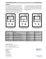
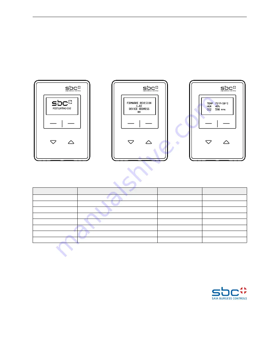
After the wall module is properly wired to the controller, it will
power up. Upon initial power up, the wall module’s LCD panel
displays three screens for two seconds each, shown in Figs. 9-11,
while the configuration file is being loaded. Once the configura-
tion file has been loaded and the startup screens have cycled
through, the LCD panel will then display the home screen. If these
screens continuously cycle, this indicates there is no program
downloaded to the controller, or the bus addresses don’t match
between the wall module and the PG5 config tool.
POWER UP
Fig. 9. PCD7.LR-TR42 Wall Module LCD
display startup screen 1.
Fig. 10. PCD7.LR-TR42 Wall Module LCD
display startup screen 2.
Fig. 11. PCD7.LR-TR42 Wall Module LCD
display startup screen 3.
For PCD7.LRxx and RoomUp users, the user interface and parame-
ters are downloaded automatically from the RoomUp tool. Refere
also to the PCD7.LRxx INSTALLATION & COMMISSIONING INSTRUC-
TIONS (PP31-401). For PCD7.LRxx-P5 users, the user interface and
parameters are downloaded from PG5 FBoxes. Refere also to the
PCD7.LRxx-P5 Manual.
Table 2. Part Descriptions
Part
Description
Sensors
Communication
PCD7.LR-TR40
Wall Module, Temp only, Sylk
Temperature
Sylk
PCD7.LR-TR40-H
Wall Module, Temp and Humidity, Sylk
Temp, Humidity
Sylk
PCD7.LR-TR40-CO2
Wall Module, Temp and CO2, Sylk
Temp, CO2
Sylk
PCD7.LR-TR40-H-CO2
Wall Module, Temp, Humdity, CO2, Sylk
Temp, Hum, CO2
Sylk
PCD7.LR-TR42
LCD Wall Module, Temp only, Sylk
Temperature
Sylk
PCD7.LR-TR42-H
LCD Wall Module, Temp and Humidity, Sylk
Temp, Humidity
Sylk
PCD7.LR-TR42-CO2
LCD Wall Module, Temp and CO2, Sylk
Temp, CO2
Sylk
PCD7.LR-TR42-H-CO2
LCD Wall Module, Temp, Humidity, CO2, Sylk
Temp, Hum, CO2
Sylk

