IG-500E
IG Device Integration Manual
1. Introduction
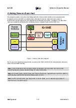
This manual covers the integration of IG-Devices such as IG-500N or IG-30G with the IG-500E. It
explains how a device, that supports the IG-Devices serial protocol, will interface with the IG-500E
and how to configure both the IG-500E and the external device. IG-Devices integration with
IG-500E is quite straightforward and does not require much configuration.
The IG-Protocol used here allows multiple sensors inputs to be connected on the IG-500E. For
example, at the same time, a remote magnetometer, a GPS receiver and an accurate barometer
can provide aiding data to the IG-500E.
With the IG-Devices protocol, you can also connect virtually any material to the IG-500E. For
example, you can connect a DVL, an USBL and a depth sensor to the IG-500E and fuse data
between these three sensors and the IG-500E.
2. Electrical connections requirements
2.1. Serial protocol
This protocol is used either on a standard RS-232 or RS-422 format (depending on device
configuration). Remote IG-Device and IG-500E ground pins must be connected together for proper
operation.
As the remote sensor can be configured by the IG-500E directly, serial line must support
bidirectional communications. In other words, both Tx and Rx pins have to be connected on the
IG-500E and on the external IG-Device. If it's not possible, please contact SBG Systems.
Transmission format:
•
Default speed : 9 600 bps (max 921 600 bps; higher baudrate is better)
•
8 bits data
•
1 stop bit
•
No parity
•
No flow control
2.2. Time pulse
If the IG-Device supports a synchronization output pin, then you should connect it to the IG-500E
Sync In or ODO In pins in order to synchronize the IG-500E with the remote IG-Device data.
SBG Systems
4/11
IG500EIIDG.3


