19
2.10 Electrical connections
See diagram of a standard installation. (§2.2 and 2.3, page 7)
Electrical connections must comply with I.E.E. Regulations.
No tension, even momentary between NEUTRAL conductor
and GROUNDED CONDUCTOR
In case of installation without Neutral
(or neutral of bad
quality), use an isolation transformer in order to create
an artificial neutral. For that, connect one outlet socket to the
ground.
All heaters must be
GROUNDED
.
Control :
XFR
heaters are controlled by
VisioLon Ind-T
programmable controller.
Refer to the technical instructions.
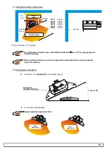
Electric cables and the electrical junction box must not be positioned in the heated area
around a heater.(see §2.7 page 16)
Types of connection cable
LINK
TYPE OF CABLE
Control unit to RP3 (and RP3 to RP3)
3-core 0.75mm
2
85°C temperature rated PVC
sheathed cable to BS6500 Table 9.
Control unit to RP32 (and RP32 to RP32)
4-core 0.75mm
2
85°C temperature rated PVC
sheathed cable to BS6500 Table 9.
RP3 or RP32 to heater
Use the BA connector supplied with the
heater
green/yellow wire: EARTH
blue wire:
NEUTRAL
brown wire:
LIVE
Control unit to sensor
Use the coaxial cable supplied by SBM.
(in 20m, 60m or 300m roles)
Number of RP3 and
RP32
units : 1 RP3 per type XFR 16, XFR 20, XFR 24 and XFR 32.
1 RP32 per type XFR 20-2, XFR 24-2 and XFR 32-2
XFR 48-2 and XFR 64-2.
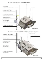
Fixing RP3 and
RP32
units : see instructions supplied in box.
230V AC
L + N + Pe
To control unit
230V AC
Always place the plastic cover back on the top of the screw head.
The RP3 or RP32 box must be located no more than 3 meters away from the ignition
block (BA block) of the heater, as the prewired plug is 3 m long.
It must not be located in the heated area around the heater
(see §2.7 page 16)
60 mm
60 mm


