ZENITH-S
MP37634
ZP90993-1
42
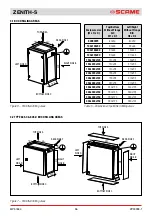
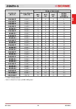
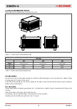
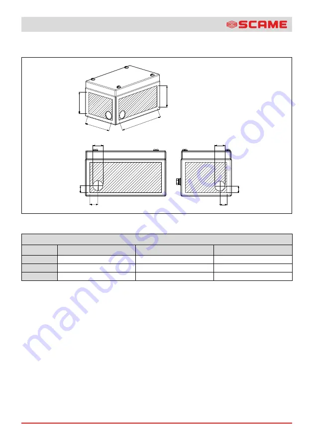
3.7 DRILLING DRAIN BREATHER POSITION
DRAIN valve shall be installed always on the bottom face side.
x
x
HOLE
HOLE
y
y
W1
H2
D1
D2
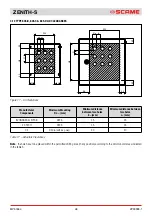
Figure 12 – Position holes for breather/drain valve
Hole Size
M16
M20
M25
HOLE
Ø16,4/16,8mm
Ø 20,5/21mm
Ø 25,5/26mm
X
16mm
16mm
20mm
Y
16mm
16mm
20mm
Table 11 - Position holes for breather/drain valve
3.8 CABLE GLANDS
Use only Ex eb and/or Ex tb IIIC approved glands (as relevant). Certified cable glands can only be fitted with a suitable IP rating
commensurate with IP rating of the enclosure.
Ensure that all the cable-glands used, shall be suitable for the cable in order to prevent self-loosening and ensure permanent
sealing to avoid moisture ingress.
3.8.1 Cable entries
Certified cable glands and blanking plug elements only to be fitted with a suitable IP rating commensurate with IP rating of the
enclosure.
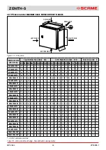
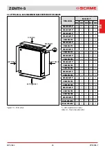
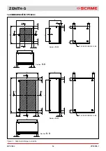
Holes can be drilled in all four face sides and the rear side.
The enclosures can be supply with flange on long side (A\C) and short side (B\D).
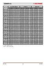
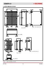
Clearances shall be maintained as specified in Table 9 - Figure 9.

