background image


19 

3.7.7.4 GASKET ACK FILTER CLEAN 

This menu option is used to acknowledge that the GASKET has been replaced or cleaned after a “CLEAN 
GASKET” alarm is displayed on the 4

th

 row of the LCD. “CLEAN GASKET” alarm will be cleared out and GASKET 

cleaning reminder will be reset after this menu is pressed. 

3.7.8   SET TIME/DATE 

This feature is used to set freezer’s time and date to ensure that all data logged has a proper time stamp. The 
program will ask the user to enter the time in HH/MM/SS format followed by the date in MM/DD/YYYY format. 
Use 

\

 key to change values and press SET key to confirm each values.


3.8 DATA LOGGING  

The data logging feature will always run as long as the ULTF control board is powered up either by 
the main power or battery backup power. This menu is used to access the sensor data that is being 
logged in the non-volatile memory of the freezer with a fixed 2-minute logging interval.  

3.8.1   SHOW TEMP LOG 

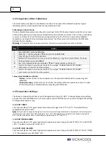
This menu consists of menu options to show the data log recorded for important temperature parameters that 
are sensed by several temperature sensors at different locations. The data log format is as follows: 

“DDMMYY HH:MMP XXX

˚

C”   

where D : date, M: month, Y: year,  H: hour, M:minute , P: AM/PM, XXX=temperature value. 
Example on CHAMBER SENSOR LOG: “280911 01:10P -88˚C” 
Example on AMBIENT SENSOR LOG: “280911 01:10P 25˚C” 
The data log will be shown from latest to oldest record. Use 

\

 to scroll up and down the recorded log data. 

The sign ‘↑’ or ‘↓’ on most bottom right of the LCD screen shows that the record list can still be scrolled 
up/down. 

3.8.2   DOWNLOAD TO USB 

This feature is used to enable transfer of data stored/logged on the Flash to a USB storage device (thumb 
drive). The user can exit by pressing the MENU key only before the USB device is connected. Once the device is 
connected and the transfer has begun, the user has to wait until the transfer is completed and he/she is 
prompted to disconnect the USB device (DISCONNECT DEVICE flashes). Once the device has been 
disconnected, the control will return to the Data logging Menu.  

Warning: 


Do not disconnect the USB storage device when the data transfer has begun. Failure to follow the 

instruction could result in system hang and losing the log data recorded.


3.8.3   CLEAR DATA LOG 

This feature is provided to enable the user to erase the stored data from the FLASH. The program 
will ask a confirmation one more time. If NO is selected then the Erase will be aborted and the 
display will return to the Data Logging Menu. Select YES to continue with the erasing process.  

Note:


The system will not respond to any key when the system is in the process of deleting the stored data

.


Warning:


The user must make sure that he/she has downloaded the stored data onto a USB storage device (Thumb Drive) 

before executing CLEAR DATALOG. Otherwise, all data previously recorded will be lost.  


Summary of Contents for Classic SCL510

Page 1: ...rature Freezer Please read this manual thoroughly to familiarize yourself with the many unique features and exciting innovations we have built into your new equipment Ultra low Temperature Freezer Sca...

Page 2: ...any appendix addendum attachment or inclusion are subject to change without notice The factory makes no representations or warranties as to the accuracy of the information contained in this manual In...

Page 3: ...2 2 Shelves Installation 8 2 2 3 Omega Brackets Installation 8 2 2 4 Remote Alarm Contacts Connection 8 2 2 5 Electrical Supply Connection and Power Protection Bracket Installation 9 2 3 First Run 9...

Page 4: ...2 General Cleaning 23 4 3 Condenser Cleaning 23 4 4 Air Filter Cleaning 24 4 5 Door Gasket Cleaning 24 4 6 Vacuum Relief Port Cleaning 24 4 7 Defrost and Cleaning 24 4 8 Backup Battery Checking and R...

Page 5: ...iii Ultra low Temperature Freezer MANUAL REVISION HISTORY REV NO DATE RELEASED DESCRIPTION OF CHANGE REFERENCE SERIAL OF 1ST UNIT FOR IMPLEMENTATION...

Page 6: ...iv...

Page 7: ...modifications to the product Consumables such as filters The factory is not liable for any damage incurred on the objects used on or stored in the equipment If the objects are highly valuable the use...

Page 8: ...the same time the equipment is delivered to the user The warranty protection extends to any subsequent owner during the warranty period Distributors who stock equipment are allowed an additional four...

Page 9: ...ion procedures and take note of the environmental electrical requirements In this manual important safety related points will be marked with the symbol If the equipment is used in a manner not specifi...

Page 10: ...viii...

Page 11: ...The freezer units feature a simple microprocessor control that allows an easy and direct set point control a heavy duty latch for secure door seal and four adjustable shelves of 45 36 kg 100 lbs capa...

Page 12: ...Vacuum Relief 3 Inner Door 4 Embedded Pulls 5 Inner Doors Magnet 6 Shelves 7 Access Port 8 Control Panel 9 Air Vents Intakes 10 Caster Wheel with Adjustable Foot 11 Cabinet Support 12 Control Probe 13...

Page 13: ...3 1 3 2 Back Quick View 1 Main Switch 2 Power Inlet 3 Remote Alarm Contact 4 Analog Output 5 Power Protection Bracket 1 2 3 5 4...

Page 14: ...4...

Page 15: ...location should be sufficiently ventilated so the heat from the unit can be removed from the area to prevent any potential overheating condition of the ambient temperature Avoid installing a unit in a...

Page 16: ...means For example in CAT II which is the category used for instruments in installations supplied from a supply comparable to public mains such as hospital and research laboratories and most industrial...

Page 17: ...Rotate shelf 45o vertically 4 Slide the shelf into the freezer chamber on top of the pilasters 5 Ensure the pilaster clips go through the holes on the shelf 1 Put the first hook 1 into the pilaster ho...

Page 18: ...se above the power cord The alarm is outputted from this terminal with contact capacity of 30 VDC 2 A The contact output is as follows Between COM and N O Between COM and N C At normal Open Close At a...

Page 19: ...cted to warm up Let the unit recover to the set temperature then load in the rest of the racks If the freezer does not require any racks let the unit run at set point for at least 48 hours for observa...

Page 20: ...10...

Page 21: ...isual user interface which shows the actual temperature inside the freezer MENU button To access the PIN authentication display or to access the menu tree directly if PIN is disabled Please refer to s...

Page 22: ...outlet is 8 C warmer than the sensed ambient temperature Low Battery LED This LED lights up when either the battery voltage is too low switch battery is not turned on or battery is not connected Other...

Page 23: ...T HIGH ALARM SET LOW ALARM RESTORE DEFAULTS CHAMBER SENSOR AMBIENT SENSOR CALIBRATE RESTORE DEFAULTS CALIBRATE RESTORE DEFAULT SET NEW PIN AUDIBLE ALARM ALARM RINGBACK TIME REMOTE ALARM DOOR ALARM TIM...

Page 24: ...m the keyed in value by pressing SET You will get CALIBRATION OFFSET STORED confirmation on the LCD from the program Temperature Stabilization Periods Startup Allow 12 hours for the temperature in the...

Page 25: ...taking the samples out open the main door and then open only one inner door at a time DOOR OPEN message will be displayed as soon as the main door is open If the main door is left open for more than...

Page 26: ...will ring The audible alarm can be muted by pressing the MUTE key 3 6 4 4 High Stage Compressor Failure This alarm is activated when the pressure switch for high stage compressor is activated This ind...

Page 27: ...o enable or disable the audible alarm The user is required to select ENABLE ALARM or DISABLE ALARM option 3 7 3 ALARM RINGBACK TIME This feature is used to determine the time after which the Audible A...

Page 28: ...P cleaning as well as to check the current reminder time interval setting The time interval provided ranges from 0 to 12 days Use key to modify the value and press SET to confirm If 0 day is chosen th...

Page 29: ...11 01 10P 25 C The data log will be shown from latest to oldest record Use to scroll up and down the recorded log data The sign or on most bottom right of the LCD screen shows that the record list can...

Page 30: ...ZER XX C 8 Heat exchanger temperature HEAT EXCH XX C 9 Condenser temperature CONDENSER XX C 10 Ambient temperature AMBIENT XX C 11 Power supply voltage AC VOLT XXX X V 12 Battery voltage BATTERY XX XV...

Page 31: ...CK COND FILTER 19 POWER FAILURE 20 WRONG INPUT FAILURE 21 HIGH ALARM 22 LOW ALARM 23 SENSOR FAILURE 24 LOW BATTERY 25 HS FAILURE 3 10 HELP Menu This menu contains quick instructions to help the user o...

Page 32: ...22...

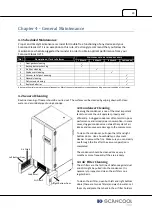
Page 33: ...ter and a mild detergent using a sponge 4 3 Condenser Cleaning Cleaning the condenser is one of the most important tasks to ensure the unit operates properly and efficiently A clogged condenser often...

Page 34: ...freezer this causes the unit to use more energy To remove the frost move all products temporarily to another freezer that operates at the same temperature as your Scancool Classic unit Turn off the po...

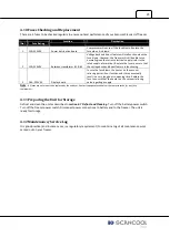
Page 35: ...AC Display board In case the fuse blown the heater on the vacuum relieving port will not function and it may eventually result in a very long door re opening time Replace the fuse to ensure that the h...

Page 36: ...26...

Page 37: ...ezer The backup system probe should be installed side by side with control probe inside the cabinet For more information on the LCO2 LN2 backup system please refer to the User Manual attached to the a...

Page 38: ...28...

Page 39: ...not work unit won t cool down at all Ensure that the power cable firmly connects the unit to the main power supply Ensure the fuse of the power cable is not blown Ensure that the unit has been turned...

Page 40: ...30...

Reviews: