78
MPS4264
Section 6: Maintenance
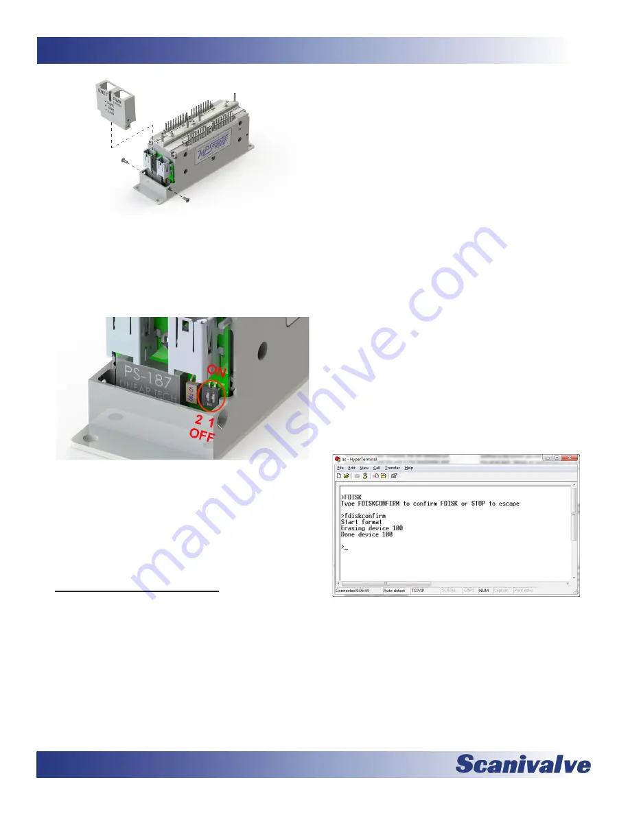
Figure 6-5: End Cover Removal
3. With the end cover removed, the DIP switches are
accessible. To hold the unit in the bootloader and
prevent it from booting into the application file,
switch the #2 DIP switch downwards to the “OFF”
position. NOTE: the switch is labeled with an “ON”
label but for this application it is backwards. “ON”
is up and “OFF” is down.
Figure 6-6: DIP Switches
4. Reconnect the power and Ethernet cables. Re-apply
power to the MPS4264. The application will not
run, but the bootloader commands can be used to
troubleshoot system problems.
5. When troubleshooting is complete, remove power
and reset switch #2 to the “ON” position. Reinstall
the end cover and re-apply power.
Formatting the Flash Disk
Should the flash disk of the MPS need to be reformatted, it
can be done fairly simply if the following procedure is care-
fully followed. For most, but not all times that an MPS will
be reformatted a serial connection needs to be available
to communicate with the unit. If you are able to currently
establish an Ethernet connection with the unit, the refor-
matting is not the best option. In that case, simply FTP to
the unit, manually delete the contents of the directory and
reload them using the procedure outlined in “Firmware
Installation & Configuration File Upload (Windows XP, 7,
10)” on page 76. However, if an Ethernet connection
cannot be established with the unit it is probably the case
that the MPS application file or memory system has been
corrupted and needs to be reformatted. The procedure for
reformatting the MPS is as follows:
1. Make sure the MPS is powered down and proper
ESD considerations are taken.
2. Following the procedure outlined in “How to
operate in bootloader mode” on page 77,
configure the DIP switch for bootloader mode with
postitioning switch #2 to “OFF.”
3. Power the MPS on. If the IP address is known, you
can attempt to connect to the unit via an Ethernet
connection. If this is not successful, or if the IP
address is not known you will need to connect using
the serial port. Details on connecting to the serial
port can be found in “Serial Communications” on
4. Once a connection is established, send the
command:
FDISK
The MPS will respond with “Type FDISKCONFIRM
to confirm FDISK or STOP to escape” Follow the
instructions and send the command:
FDISKCONFRM
The MPS will respond indicating completion:
Start format
Erasing device 100
Done device 100
>
Figure 6-7: FDISK command
Summary of Contents for MPS4264
Page 1: ...MPS4264 Miniature Pressure Scanner Hardware and Software Manual Software Version 2 07...
Page 2: ......
Page 3: ......
Page 6: ...INTENTIONALLY LEFT BLANK...
Page 12: ...6 MPS4264 Section 1 Specifications INTENTIONALLY LEFT BLANK...
Page 18: ...12 MPS4264 Section 2 Introduction INTENTIONALLY LEFT BLANK...
Page 32: ...26 MPS4264 Section 4 Hardware INTENTIONALLY LEFT BLANK...
Page 38: ...32 MPS4264 Section 5 Software INTENTIONALLY LEFT BLANK...
Page 81: ...75 MPS4264 Section 6 Maintenance INTENTIONALLY LEFT BLANK...
Page 86: ...80 MPS4264 Section 6 Maintenance INTENTIONALLY LEFT BLANK...
Page 87: ...81 MPS4264 Appendix INTENTIONALLY LEFT BLANK...


