Document type
Document number
Rev
Page
Manual
66024
C
27 of 37
5
Installation Instructions
5.1
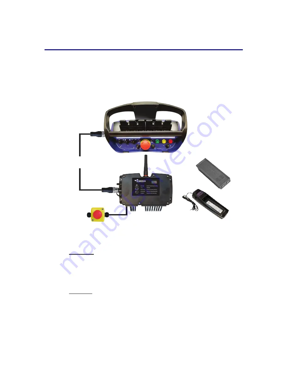
General schematic of the RC 400
When the Scanreco RC 400 is installed an electrically controlled dump valve must, for
reasons of safety, always be connected between the manoeuvre valve and the tank.
This means that during an emergency stop manoeuvre the dump valve will be
without power and will transfer the pump flow directly to the tank thus making the
system entirely without hydraulic pressure.
Figure 5.1
5.2
Important notice during welding
Important: It is sometimes necessary to weld a truck/machine. During welding the
system's electrical connections must always be disconnected from other equipment,
i.e. power supply cables (+ and -), all valve contacts, the EX cables contact must be
disconnected.
5.3
Locating the central unit
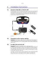
Important: The central unit must be mounted in accordance with the
recommendations given below (see figure 5.2). To ensure the longest possible life for
the central unit and its cables, the central unit must always be mounted so that the
valve contacts are located facing downwards. The central unit must not be mounted
so that the cables face upwards. The reason for this is to hinder water from running
via the cables, towards the central unit
(The cables on the central unit are thus not subjected to long periods of accumulated
water, damp, salt etc). The central unit should be mounted in a vibration free
location and not close to strong heat sources (for example exhaust pipes etc).
6
7
8
3
4
2
1
5
27/37
Summary of Contents for RC400
Page 1: ...Instruction Manual RemoteControlSystemRC400 Document 66024 Revision D Language English ...
Page 2: ......
Page 39: ......
Page 40: ......


