Document type
Document number
Rev
Page
Manual
66024
C
34 of 37
6.3.2
Error codes
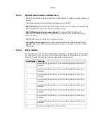
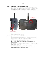
The Central Unit will indicate detected errors via the double 7-segment LED display.
If the Central Unit detects an error it will be indicated by the LED STATUS flashing
red whilst the the double 7-segment LED display indicates the error code with the
digits “Er” followed by four digits in two blocks with the corresponding error code.
Example on error code sequence:
“Er” -> “15” ->”1A” -> ““Er” -> “15” ->”1A” ->“Er” -> “15” ->”1A” ->
The error code sequence will repeat itself three times if the error is considered a soft
error and reboot to standby mode, if the error is considered a hard error the error
code sequence will be continued until supply power is disconnected.
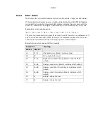
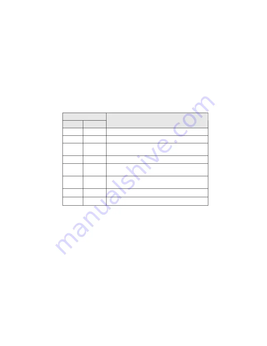
Below list over error codes and their meaning
Indication
Block 1 Block 2
Meaning
01.
01-07
Checksum error (Block 2 declares type)
02.
02
DV output short circuit
04.
01-14
Digital output short circuit (Block 2 declares which
output)
07.
1A-8B
Analog output error (Block 2 declares which output)
15.
1A-8B
Analog output short circuit (Block 2 declares which
output)
16.
1A-8B
Analog output interruption (Block 2 declares which
output)
17.
01
Supply voltage too low
17.
02
Supply voltage too high
34/37
Summary of Contents for RC400
Page 1: ...Instruction Manual RemoteControlSystemRC400 Document 66024 Revision D Language English ...
Page 2: ......
Page 39: ......
Page 40: ......

