background image


COMPACT 75


COMPACT 75                                   

Operator’s manual for drilling machine


- 9 - 

5.  OPERATING INSTRUCTIONS 

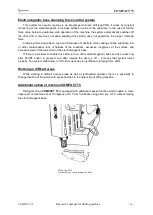
The  drilling  machine  has  a  spindle  with  Morse  Taper  MT3  to  use  twist  drill  (by  using  the 

reduction adapter if necessary)  and  annular c

utters. Arbor mark AMT is mounted in spindle conical 

taper to fix annular cutters. 

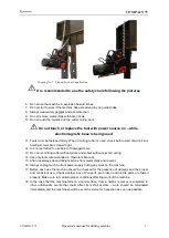
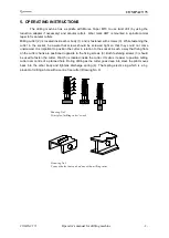
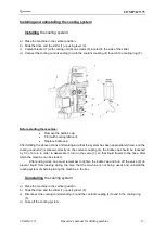
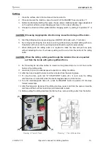
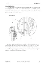
Milling cutter (2) is located inside arbor body (1) and is fastened with screws (3). While fastening the 

cutter in the socket, be aware that screws should be screwed tight so that they could not come 
unscrewed. It is important to position the cutter in relation to the socket in such a way that fixing flats 

on the cutter shank are positioned opposite to the fixing screws (3). Both fastening screws (3) should 

be used to fasten 

the cutter. Pilot (5) is located inside the cutter. It makes it easier to position milling 

cutter over centre of a planned hole. During drilling as the cutter goes deep into steel, the pilot moves 

back  into  the  arbor  body  and  tightens  discharge  spring  (4).

  That spring ejects slug which is a by-

product of milling a hole with a centre free cutter (Drawing No. 3).
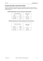


Drawing No 3 

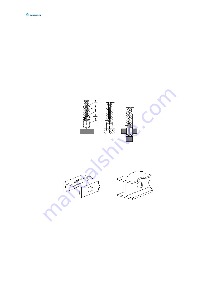
Types of holes that can be done with a milling cutter 


Drawing No 2. 

Principle of milling cutter’s work 


Summary of Contents for COMPACT 75

Page 1: ... 9 DK 9460 Brovst DENMARK Tel 45 98 23 60 88 Fax 45 98 23 61 44 Website www scantool group com E mail info scantool group dk SAFETY INSTRUCTIONS AND OPERATORS MANUAL FOR DRILLING MACHINE C CO OM MP PA AC CT T 7 75 5 ...

Page 2: ...NSTRUCTIONS 9 6 INSTALLING AND UNINSTALLING THE ARBOR 10 7 INSTALLING AND UNINSTALLING THE MILLING CUTTER 11 8 MAGNETIC DRILLING MACHINE START UP 12 9 MAINTENANCE AND SERVICE 23 10 ELECTRICAL DIAGRAM 26 11 SPLIT DRAWING AND SPARE PARTS LISTS 27 12 CE DECLARATION OF CONFORMITY 37 BEFORE YOU START WORK WITH THE MACHINE PLEASE READ THESE INSTRUCTIONS CAREFULLY AND USE ALL RECOMMENDATIONS ...

Page 3: ...nce shop etc But full advantages of electromagnetic drilling machines can be achieved only with optimal tooling Milling cutters are designed and manufactured specifically for use with these machines and offer a whole range of advantages such as 4 inch diameter holes through more than 2 inch steel in one pass and with precision not otherwise attainable without heavy stationary equipment The COMPACT...

Page 4: ...rill diameter 8 32 mm 5 16 1 Max annular drill diameter 12 75 mm 1 2 3 Max milling depth 76 mm 3 Maximum tap size M24 G3 4 Protection class Class I Standard adhesive force of electromagnet for steel 7 8 22 mm thick and Ra 1 25 19 500 N Slide stroke 225 mm Rotational speed under load I gear 80 160 rpm II gear 210 420 rpm Electromagnetic base 110x220x56 mm Length of the power cord 3 0 m Total weight...

Page 5: ...which consists of metal box 1pc drilling machine 1pc arbor AMT3 U 19 3 3 1pc cooling system 1pc chip guard 1pc spoke handles 3pcs hex wrench s 2 5 1pc hex wrench s 4 1pc hex wrench s 5 1pc hex wrench s 6 1pc hex wrench s 10 8 mm flat wrench 1pc wedge MT3 1pc safety chain with snap hook 1pc operator s manual 1pc ...

Page 6: ...the immediate vicinity of machine Warning Read and save all instruction for future reference Important rules of safe use drilling machine on electromagnetic base 1 Before attempting to work with the machine check the condition of electrical installation including power cord and plug 2 The drilling machine should be connected to an installation equipped with protection circuit grounding and protect...

Page 7: ...damaged tools 13 Do not use milling cutter without pilots and arbors without ejection spring 14 Use only tools recommended in Operator s Manual 15 After use always clean drilling machine from metal chips and coolant 16 Always unplug machine from power supply during any work on the machine 17 Before each use the machine should be checked for the presence of damage and the proper and consistent use ...

Page 8: ... or individuals injury The machine should be located on the work piece with the entire surface of the electromagnetic base It is recommended that each time before positioning the machine surface under the electromagnetic base should be sanded down with abrasive paper Thickness lower than 5 mm Magnetic Drilling Machine COMPACT 75 will not start because of CLAMPING FORCE CONTROL SYSTEM Warning Read ...

Page 9: ...me unscrewed It is important to position the cutter in relation to the socket in such a way that fixing flats on the cutter shank are positioned opposite to the fixing screws 3 Both fastening screws 3 should be used to fasten the cutter Pilot 5 is located inside the cutter It makes it easier to position milling cutter over centre of a planned hole During drilling as the cutter goes deep into steel...

Page 10: ... fin on top and place it in the spindle 5 By turning the arbor align the fin to the appropriate slot in the spindle 6 Using a light impact from the bottom side drive the arbor into the spindle Uninstalling the arbor 1 Raise the guard turn the spindle so that the wedge MT opening in the spindle 1 is lined up with the wedge MT opening in the reducer body 2 Place the wedge MT included as standard equ...

Page 11: ...attain access to the arbor 4 screws 5 3 Insert the appropriate type of pilot 6 into the milling cutter 7 4 Position the milling cutter 7 with the cutter facing up so that the flat sides of the milling cutter are found facing the screws 5 5 Put the milling cutter 7 into the arbor socket 4 6 Tighten the screws securely 5 Uninstalling the milling cutter 1 Raise the drive and the slide 2 up using the ...

Page 12: ...lux Thickness of work piece is at least 10 mm 3 8 Surface of steel under the magnet is flat Wipe brush or sand down clean surface where you intended to place the drilling machine so that you remove rust paint dirt etc which would reduce adhesive power of the electromagnetic base Preparation the machine for drilling 1 Set the drilling machine on the surface of the element which hole is to be drille...

Page 13: ...in another drilling position than vertical the cooling liquid must be provided manually 6 Define the direction of the spindle rotation 7 Set proper rotational speed according to the type of the tool and working material 8 Connect the drilling machine to electric network according to 9 Set the axis of the spindle right above drilling point in the case of milling cutter the end of the pilot helps wi...

Page 14: ...erial does not bow one can try to carry out drilling of a hole although with keeping the strictest precautions Particularly a magnitude of a pushing force on a feed handle should be very limited Appropriate rpm should be adjusted depending on if drilling would be carried out with a drill bit or with trepan type metal cutter and a metal cutter s diameter A drive is equipped in mechanical 2 step red...

Page 15: ...COMPACT 75 COMPACT 75 Operator s manual for drilling machine 15 Drawing 4 Clamping force depending on the thickness of the substrate and the value gap ...

Page 16: ...ness of the surface and excessive wear of the lower part of the electromagnetic base If there is a problem to enable drive after turn on of the electromagnetic base so drive works only after START button is pressed and after release the drive is off it means that system works properly The system didn t allow to for further work due to insufficient clamping force drills Working in difficult areas W...

Page 17: ...the system has been appropriately fixed and the cooling conduit 2 is placed correctly on the coolant coupling 4 the bottle cap should be loosened by 1 3 of a turn in order to deaereate it turn on the valve 3 so that liquid travels to the hose after which the machine can be started After ending work one must remember to tighten the bottle cap and turn off the valve 9 to prevent liquid from leaking ...

Page 18: ...gearbox speed should be changed For example if machine worked with 160 rpm speed it should be switched to 420 rpm Relationship between machine speed and cutter diameter Relationship between machine speed and twist drill diameter The twist drill diameter Rotary Speed rpm inch mm 0 70 1 25 18 32 80 160 0 30 0 70 8 17 210 420 The cutter diameter Rotary speed rpm inch mm 1 38 3 00 35 75 80 160 0 50 1 ...

Page 19: ...COMPACT 75 COMPACT 75 Operator s manual for drilling machine 19 ...

Page 20: ...st one pass without retracting the tool It will ease pushing out the core from the inside of the milling cutter CAUTION When the milling cutter goes through the material the core is pushed out from the inside with quite significant force 8 For the safety do not allow neither to create too long metal chips nor to roll them on the holder or the milling cutter 9 Use knob 03 to set rotational speed re...

Page 21: ...tation by the switch 02 and change the direction of rotation by switch 05 7 Start the rotation and carefully put the tap outside the hole 8 Stop the motor 9 Replace the tap to no 3 size change the direction of rotation and repeat activity from point 4 to 8 The machine allows making threading to the extent specified in the technical data To perform tapping is recommended to use threads for hand thr...

Page 22: ... the material then start the machine again by pressing green button 02 MOTOR START STOP Do not switch off electromagnetic base 01 MAGNET switch to prevent accidental movement of the drilling machine from the axis of the drilled hole Changing direction of rotation Changing the direction of rotation should be performed by switch 05 with stopped spindle rotation Switch 05 pressed to O position will t...

Page 23: ...should be replaced for original new ones After replacement new brushes should be run in without load for about 20 min Other repair work should be done only by authorized service points appointed by distributor Replacement of brushes is possible without removal motor unit from the unit Lubricate regularly brass slide guide inserts with grease as well as the rack and pinion To prevent the machine fr...

Page 24: ...wn several times so that the pressure strip aligns itself and cancels clearance After carrying out these activities and canceling clearance tighten screws 2 starting from the middle screw The slider should be located symmetrically relative to the middle screw Next tighten the neighboring screws 2 moving the slider in the degree necessary for making them visible Then tighten screws 3 until any noti...

Page 25: ...f the motor brushes from the connector 6 using the flat ending 5 of the lead The ending has a safeguard against its sliding down first press the protruding element at the middle of the ending then carefully slide off the ending from the connector 4 Push aside the spring arm 7 pressing down the brush and rest it on the surface of the brush holder 8 and remove the brush 9 5 Inspect brush length if t...

Page 26: ...COMPACT 75 COMPACT 75 Operator s manual for drilling machine 26 10 ELECTRICAL DIAGRAM COMPACT 75 ...

Page 27: ...L RETAINING RING 28z 1 15 PDK 000060 SPRING WASHER 4 3 1 16 PDK 000043 SPRING WASHER 4 1 5 17 PDK 000151 NYLON WASHER SR1940 4 18 WKR 000395 SOCKET BUTTON HEAD CAP SCREW WITH FLANGE M5x20 2 19 WKR 000184 SCREW M4X12 PHCRMS 4 20 NKL 0272 15 00 00 0 LABEL FOR ELECTRICAL INSTALATION 1 21 WKR 000415 CROSS RECESSED PAN HEAD TAPPING SCREW 3 5x13 4 22 PDK 000161 SPRING WASHER EXTERNAL STAR 3 7 4 23 NKL 0...

Page 28: ...COMPACT 75 COMPACT 75 Operator s manual for drilling machine 28 ...

Page 29: ...ATE ARM 1 1 6 WLK 0153 02 04 00 0 ECCENTRIC SWIVEL BASE SHAFT 1 1 7 NKR 0153 02 05 00 0 SPECIAL NUT 1 1 8 PDK 0153 02 06 00 0 Special washer MT3 V2 1 1 9 SRB 0165 01 03 00 0 SPECIAL BOLT 1 1 10 PRS 000013 Ext retaining ring MT3 V2 2 1 11 PDK 000048 SPRING WASHER 6 1 3 1 12 PDK 000051 SPRING WASHER 8 2 4 1 13 SRB 000255 HEX SOCKET BOLT M5x10 1 1 14 SRB 000117 HEX SOCKET BOLT M6x25 3 1 15 SRB 000153...

Page 30: ...1 1 1 2 LST 0473 01 01 02 0 PRESSURE PLATE 1 1 1 3 LST 0400 01 01 03 0 SLIDE INSERT 1 1 1 4 TLJ 000010 SELF LUBRICATING SLEEVE 28 05H7x32x16 2 1 1 5 SPR 000043 SPRING 1 6x8x14 5 4 1 1 6 SRB 000086 HEX SOCKET BOLT M5X20 5 1 1 7 PDK 000017 ROUND WASHER 5 3 5 1 1 8 WKR 000077 SOCKET SET SCREW M5x16 4 1 1 9 NKR 000016 HEX NUT M5 4 1 1 10 TLJ 000014 SELF LUBRICATING SLEEVE 21H7 24 16 2 ...

Page 31: ... 1 2 13 TLJ 0171 00 22 00 0 SHIFT DRIVE PIN 1 2 14 SPR 0171 00 23 00 0 COMPRESSION SPRING 1 2 15 DZW 0171 00 24 00 0 SHIFT LEVER 1 2 16 TRC 0171 05 00 00 0 IMPULSING SHIELD ASSY 1 2 17 WDL 0211 00 28 00 1 SHIFT FORK 1 2 18 TBL 0202 00 30 00 0 LABEL SHIFT LEVER 1 2 19 PRS 000017 EXTERNALE RETAINING RING 25z 1 2 20 WPS 000054 KEY 6x6x20 1 2 21 KLK 000004 SPRING PIN 3x12 1 2 22 PDK 000045 SPRING WASH...

Page 32: ...COMPACT 75 COMPACT 75 Operator s manual for drilling machine 32 ...

Page 33: ...UPLING AMT2 H 19 1 2 2 4 LOZ 000034 UPPER SPINDLE BEARING 6000 2Z P6 S 10x26x8 2 2 2 5 LOZ 000051 UPPER SPINDLE BEARING 6007 ZZ 35x62x14 1 2 2 6 LOZ 000108 BEARING 6205 LLU 25x51x15 1 2 2 7 PRS 000077 SEAL 35x55x10 1 2 2 8 PRS 000081 SEAL 35x56x12 1 2 2 9 PRS 000024 EXTERNAL RETAINING RING 35Z 1 2 2 10 PRS 000035 INTERNAL RETAINING RING 62W 1 2 2 11 KLK 000045 DOWEL PIN 5 x 12 MM 1 2 2 12 WKR 0004...

Page 34: ...400 02 02 12 1 HELICAL INPUT GEAR z47 m 1 m 17 1 2 3 3 WPS 0211 00 17 00 0 WOODRUFF KEY 3x3 7 1 2 3 4 LOZ 000071 UPPER SPINDLE BEARING 628 2Z NTN 8x24x8 1 WLK 0400 02 02 20 0 PINION SHAFT z12 m 1 5 ASSY ITEM PART NUMBER VERSION DESCRIPTION Q TY 2 4 1 WLK 0400 02 02 21 0 PINION SHAFT z12 m 1 5 1 2 4 2 KOL 0400 02 02 22 0 SHIFT WHEEL z 43 1 2 4 3 WPS 000055 KEY 4x4x45 1 2 4 4 LOZ 000071 UPPER SPINDL...

Page 35: ...RT NUMBER VERSION DESCRIPTION Q TY 3 1 MSK 0473 03 01 00 0 PANEL PLATE 1 3 2 NKL 0473 10 01 01 0 PANEL PLATE LABEL 1 3 3 PRC 000007 SWITCH START STOP 1 3 4 WZK 0400 03 02 00 0 START STOP WIRE 1 3 5 PNK 000013 SWITCH MAGNET 1 3 6 WZK 0473 03 03 00 0 r p m WIRE 1 3 7 WZK 0473 03 04 00 0 L R WIRE 1 1 2 3 4 5 7 6 ...

Page 36: ...RT NUMBER VERSION DESCRIPTION Q TY 10 1 KRP 0173 00 01 00 0 ARBOR BODY 1 10 2 WKR 000032 HEX SET SCREW M10X10 2 10 3 PRS 000009 INTERNAL RETAINING RING 19W 1 10 4 PDK 0139 00 04 00 0 WASHER D 18 8x10x1 1 10 5 USZ 0140 05 04 00 0 SEAL 1 10 6 WYP 0154 00 02 00 0 PLUNGER 1 10 7 SPR 0154 00 03 00 0 SPRING 1 6x12 4x159 1 ...

Page 37: ...onsibility that product COMPACT 75 DRILLING MACHINE are manufactured in accordance with the provisions of the European Parliament and Council Directive 2006 42 EC of 17 May 2006 And also in accordance with Low Voltage EUROPEAN PARLIAMENT AND COUNCIL DIRECTIVE 2014 35 EU of 26 February 2014 EMC EUROPEAN PARLIAMENT AND COUNCIL DIRECTIVE 2014 30 EU of 26 February 2014 ___________________________ Chai...

Reviews: