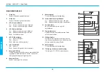
PARTS DESCRIPTION
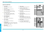
1.
IR transmitter
Sends infrared signals straight up.
2.
IR transmitter
Sends infrared signals straight forward.
3.
LED / Power indicator
ON: External power supply connected.
OFF: External power supply disconnected.
4.
LED / Battery indicator
ON: Battery power supply connected.
OFF: Battery power supply disconnected.
Flash: Low battery level.
5.
LED / GSM indicator
ON: No GSM signal.
OFF: Normal.
Flash: SIM-card / GSM module error.
6.
LED / IR indicator
OFF: Normal.
Flash: Sends IR signals to heat pump.
7.
GSM test button
Press the button to read current GSM signal strength.
GSM indicator flashes from 1 (low) to 10 (high) times,
depending on signal strength.
8.
IR test button
Sends a test signal from the unit.
9.
Mounting hole
For easy installation with wall bracket.
10.
Internal power supply switch
ON: Battery power supply activated.
OFF: Battery power supply deactivated.
11.
Service cover
Compartment for the battery switch and
SIM-card holder.
12.
Temperature sensor
Reads current room temperature. Do not
block this hole.
13.
SIM-card holder
When installing the SIM-card the internal
power supply switch must turned OFF and
the external power supply be disconnected.
14.
Mounting hole
For easy installation with wall bracket.
15.
External power supply connection
.
Connection for 12V DC, 1A power adapter.
GETTING STARTED
2
1
2
3
4
5
6
7
8
9
10
11
13
12
14
15
ENGLISH
Summary of Contents for LINK
Page 1: ......
Page 11: ...SUOMI 11 ...
Page 21: ...SVENSKA 11 ...
Page 31: ...DANSK 11 ...
Page 41: ...ENGLISH 11 ...
Page 42: ...THIS PAGE IS INTENTIONALLy LEFT bLANK ...
Page 43: ...THIS PAGE IS INTENTIONALLy LEFT bLANK ...
Page 44: ......

