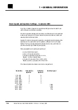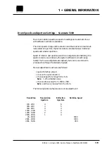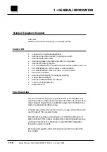
Control board
Signal
Test Point
Red
TP46
Green
TP47
Blue
TP48
Sync.
TP57
Ground
TP100
Refer to section 7•7 for location of the fuses and test points on the driver
board, and 7•5 for test points on the control board.
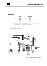
Optical System Block Diagram
1 • GENERAL INFORMATION
Edition 1
•
January 1996 Service Manual • ScanMate 4000/5000
1•7
Drum
Blue
PMT’s
TP48
TP47
TP46
TP57
clk
Amps
and
AD
converters
Control
board
All test points are located on the control board
CPU/SCSI
Green
Red
Original
DC motor
Encoder
Sync.
signal
Sensor
Focus motor
Aperture motor
Fibre
optics
Fibre
optics
Trans-
mission
light
Reflec-
tion
light
Light tube
Beam
splitter
and
filters
Summary of Contents for ScanMate 4000
Page 1: ...ScanMate 5000 ScanMate 4000 ...
Page 6: ......
Page 16: ......
Page 18: ......
Page 20: ......
Page 22: ......
Page 24: ......
Page 28: ......
Page 40: ......
Page 44: ......
Page 48: ......
Page 52: ......
Page 56: ......
Page 60: ......
Page 64: ......
Page 68: ......
Page 72: ......
Page 76: ......
Page 80: ......
Page 84: ......
Page 88: ......
Page 92: ......
Page 96: ......
Page 100: ......
Page 102: ......
Page 106: ......
Page 110: ......
Page 114: ......
Page 118: ......
Page 122: ......
Page 126: ......
Page 130: ......
Page 134: ......
Page 138: ......
Page 142: ......
Page 146: ......
Page 150: ......
Page 154: ......
Page 156: ......
Page 162: ......
Page 164: ......
Page 170: ......
Page 171: ...ScanMate 4000 Type 250 Circuit Connection Diagram ...
Page 172: ...ScanMate 5000 Type 210 Circuit Connection Diagram ...
Page 174: ......


