How to test
1
• Fit a terminator to one SCSI connector on the scanner and SCSI
cable and RS 232 service cable to the scanner and PC.
2
• Set the Dip switch to 8, (on).
3
• Turn on the PC or Mac and access the service program main menu
(section 3•5).
4
• Mount the UGRA test target firmly onto the drum.
5
• Switch on the scanner and start up Photoshop plug-in.
6
• Make a preview of the UGRA test target.
7
• Perform a focus calibration on the target.
8
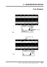
• Crop an area of the test target with the 12 circles as shown in fig. 1.
9
• Choose the following settings in Photoshop:
Transmission gray scale.
Aperture 1
Neutral gradation curve
Gamma 0.78
600 dpi resolution.
White/black point:
max. 255
min. 0
10
• Make a scan of the area.
11
• Select
Adjust levels
in Photoshop image menu.
12
• Define the background of the circles in the
Levels
window by
clicking on the white marker
A
and moving it to the right peak of
the histogram as shown in fig. 1.
Note:
adjustment must be at least 250 for white point.
13
• Select
Map threshold
in Photoshop image menu.
14
• Click on the marker in the
Threshold
window and set a value of
128 (fig. 2).
15
• For correct sharpness of focus, a few pixels should be visible down
to at least 6 microns.
Note
: Interpretation of pixel saturation is difficult, however fig. 2
gives a guideline of how the spread should appear. Be aware that
dust on the test target can give false indications.
Service Manual • ScanMate 4000/5000 Edition 1
•
January 1996
Focus Sharpness
5•11b
Summary of Contents for ScanMate 4000
Page 1: ...ScanMate 5000 ScanMate 4000 ...
Page 6: ......
Page 16: ......
Page 18: ......
Page 20: ......
Page 22: ......
Page 24: ......
Page 28: ......
Page 40: ......
Page 44: ......
Page 48: ......
Page 52: ......
Page 56: ......
Page 60: ......
Page 64: ......
Page 68: ......
Page 72: ......
Page 76: ......
Page 80: ......
Page 84: ......
Page 88: ......
Page 92: ......
Page 96: ......
Page 100: ......
Page 102: ......
Page 106: ......
Page 110: ......
Page 114: ......
Page 118: ......
Page 122: ......
Page 126: ......
Page 130: ......
Page 134: ......
Page 138: ......
Page 142: ......
Page 146: ......
Page 150: ......
Page 154: ......
Page 156: ......
Page 162: ......
Page 164: ......
Page 170: ......
Page 171: ...ScanMate 4000 Type 250 Circuit Connection Diagram ...
Page 172: ...ScanMate 5000 Type 210 Circuit Connection Diagram ...
Page 174: ......


