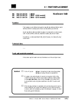
How to replace
Removal
1
• Remove the following covers:
Lamp cover
A
and back cover
B
, (section 4•2 steps 1-2).
2
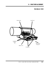
• Remove the two 2.5 mm countersunk screws
A
on each side of the
hardware unit and carefully slide the unit partially out.
3
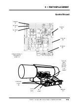
• Remove the CPU module by lifting away from connectors J12 and
J13 on the control board.
Assembly
4
• Fit the new CPU module onto connectors J12 and J13 on the control
board.
Note:
in isolated cases, it is possible to fit the module both ways,
therefore it is important that the side with the SCSI controller is to
the
right hand side
as viewed from the
back
of scanner.
5
• Partially refit the hardware unit, (section 4•5 steps 7-10).
6
• Carry out the adjustment and test operations specified below.
7
• Carefully push the hardware unit fully in, (connector J1 on the driver
board mates with the backplane) and fit the two 2.5 mm counter-
sunk allen screws
A
on each side of the unit.
8
• If no further replacement operations are required refit the covers
removed in step 1 in accordance with section 4•2.
Adjustments and tests required
White calibration in transmission and reflection (section 5•5).
Focus calibration (section 5•4).
Register error (section 5•12).
Stripes in shadow (section 5•13).
Service Manual • ScanMate 4000/5000 Edition 1
•
January 1996
CPU Board
4•7b
Summary of Contents for ScanMate 4000
Page 1: ...ScanMate 5000 ScanMate 4000 ...
Page 6: ......
Page 16: ......
Page 18: ......
Page 20: ......
Page 22: ......
Page 24: ......
Page 28: ......
Page 40: ......
Page 44: ......
Page 48: ......
Page 52: ......
Page 56: ......
Page 60: ......
Page 64: ......
Page 68: ......
Page 72: ......
Page 76: ......
Page 80: ......
Page 84: ......
Page 88: ......
Page 92: ......
Page 96: ......
Page 100: ......
Page 102: ......
Page 106: ......
Page 110: ......
Page 114: ......
Page 118: ......
Page 122: ......
Page 126: ......
Page 130: ......
Page 134: ......
Page 138: ......
Page 142: ......
Page 146: ......
Page 150: ......
Page 154: ......
Page 156: ......
Page 162: ......
Page 164: ......
Page 170: ......
Page 171: ...ScanMate 4000 Type 250 Circuit Connection Diagram ...
Page 172: ...ScanMate 5000 Type 210 Circuit Connection Diagram ...
Page 174: ......

