Function
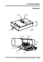
The PMT module is common to the ScanMate 4000 and 5000, (both
0200 and 0210 models) and contains three photo multiplier tubes which
convert the light to electronic signals. The signal is then transmitted to
the control board.
Technical data
Three PMT’s, one each for each color channel.
Tools and materials required
1.5 mm allen key for fibre optic cables set screws
2 mm allen key for back cover and hardware unit mounting screws
2.5 mm allen key for PMT module mounting screw
4 • PART REPLACEMENT
PN
960 20 000 50
(4000/5000)
PMT Module
Edition 1
•
January 1996 Service Manual • ScanMate 4000/5000
4•11a
Caution!
☛
Turn off power
• Before
connecting or disconnecting cables.
• Before
carrying out service operations.
☛
If a green colored connector is used in connection J20 on the
control board, ensure that is reconnected with the locking tabs
on the
right hand side
, viewed from the
back
of the scanner. If
reconnected incorrectly, the amplifiers in the PMT module will
blow.
☛
Avoid excessive bending or otherwise damaging the fibre optics
cables.
Summary of Contents for ScanMate 4000
Page 1: ...ScanMate 5000 ScanMate 4000 ...
Page 6: ......
Page 16: ......
Page 18: ......
Page 20: ......
Page 22: ......
Page 24: ......
Page 28: ......
Page 40: ......
Page 44: ......
Page 48: ......
Page 52: ......
Page 56: ......
Page 60: ......
Page 64: ......
Page 68: ......
Page 72: ......
Page 76: ......
Page 80: ......
Page 84: ......
Page 88: ......
Page 92: ......
Page 96: ......
Page 100: ......
Page 102: ......
Page 106: ......
Page 110: ......
Page 114: ......
Page 118: ......
Page 122: ......
Page 126: ......
Page 130: ......
Page 134: ......
Page 138: ......
Page 142: ......
Page 146: ......
Page 150: ......
Page 154: ......
Page 156: ......
Page 162: ......
Page 164: ......
Page 170: ......
Page 171: ...ScanMate 4000 Type 250 Circuit Connection Diagram ...
Page 172: ...ScanMate 5000 Type 210 Circuit Connection Diagram ...
Page 174: ......


