How to replace
Removal
1
• Remove the following covers:
Left hand end plate
E
and left hand drum cover
F
, (section 4•2 steps
5 and 6).
2
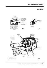
• In order to give access to the spindle step motor, move the drum to
the zero position, turn on power and access the service program,
(section 3•5).
3
• Select
1
, (
Move spindle
) and
Z
, (
Set drum in zero position
). Turn off
power.
4
• Disconnect the connector to the step motor.
5
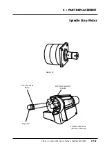
• Manually rotate the spindle until the head of the 4 mm dome head
allen screw
A
securing the step motor to the spindle is accessible
and remove the screw and lock washer.
6
• Remove the four 4 mm allen screws
B
retaining the step motor to
its mounting bracket and lift the motor away.
Assembly
7
• Mount a new step motor and refit the four 4 mm allen screws.
8
• Align the holes in the step motor shaft and spindle and refit the 4
mm dome head allen screw and new lock washer.
9
• Reconnect the connector to the step motor.
10
• Carry out the adjustment and test operations specified below.
11
• If no further replacement operations are required, refit the covers
removed in step 1 in accordance with section 4•2.
Adjustments required
White calibration in transmission and reflection (section 5•5)
Register error (section 5•12).
Service Manual • ScanMate 4000/5000 Edition 1
•
January 1996
Spindle Step Motor
4•14b
Summary of Contents for ScanMate 4000
Page 1: ...ScanMate 5000 ScanMate 4000 ...
Page 6: ......
Page 16: ......
Page 18: ......
Page 20: ......
Page 22: ......
Page 24: ......
Page 28: ......
Page 40: ......
Page 44: ......
Page 48: ......
Page 52: ......
Page 56: ......
Page 60: ......
Page 64: ......
Page 68: ......
Page 72: ......
Page 76: ......
Page 80: ......
Page 84: ......
Page 88: ......
Page 92: ......
Page 96: ......
Page 100: ......
Page 102: ......
Page 106: ......
Page 110: ......
Page 114: ......
Page 118: ......
Page 122: ......
Page 126: ......
Page 130: ......
Page 134: ......
Page 138: ......
Page 142: ......
Page 146: ......
Page 150: ......
Page 154: ......
Page 156: ......
Page 162: ......
Page 164: ......
Page 170: ......
Page 171: ...ScanMate 4000 Type 250 Circuit Connection Diagram ...
Page 172: ...ScanMate 5000 Type 210 Circuit Connection Diagram ...
Page 174: ......


