background image

26

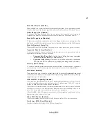
Using BIOS

Press DEL to enter SETUP

Pressing the delete key accesses the BIOS Setup Utility:

  Advanced Chipset Features

              Load Optimized Defaults

  PC Health Status

              Exit Without Saving

Phoenix-AwardBIOS CMOS Setup Utility:

Standard CMOS Features

   Frequency/Voltage Control

Esc:  Quit

:  Select Item

F10: Save & Exit Setup

Time, Date, Hard Disk Type...

 Advanced BIOS Features

             Load Performance Defaults

 Integrated Peripherals

              Set Supervisor Password

  Power Management Setup

             Set User Password

  PnP/PCI Configurations

              Save & Exit Setup

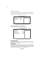
KEY

FUNCTION

ESC

Exits the current menu

Scrolls through the items on a menu

+/-/PU/PD

Modifies the selected field’s values

F10

Saves the current configuration and exits setup

F1

Displays a screen that describes all key functions

F5

Loads previously saved values to CMOS

F6

Loads performance defaults

F7

Loads an optimum set of values for peak performance

BIOS Navigation Keys

The BIOS navigation keys are listed below:

Summary of Contents for K8T800Pro-A

Page 1: ......

Page 2: ......

Page 3: ...and found to comply with the limits for a Class B digital device pursuant to Part 15 of the FCC Rules These limits are designed to provide reason able protection against harmful interference in a resi...

Page 4: ...et appareil num rique de la classe B respecte toutes les exigences du R glement sur le mat riel brouilieur du Canada AbouttheManual The manual consists of the following Chapter 1 Introducing the Mothe...

Page 5: ...Jumper Settings 9 Jumper Settings 9 Connecting Case Components 10 Front Panel Connector 12 InstallingHardware 13 Installing the Processor 13 Installing Memory Modules 14 Installing a Hard Disk Drive C...

Page 6: ...d 44 Save Exit Setup Option 45 Exit Without Saving 45 Chapter 4 47 47 47 47 47 UsingtheMotherboardSoftware 47 AbouttheSoftwareCD ROM 47 Auto installing underWindows 98 ME 2000 XP 47 Running Setup 48 M...

Page 7: ...ansfer rate The K8T800Pro Northbridge interconnects to the South Bridge through the high speed 8X 66 MHz 533 MB sec V Link interface The VT8237 Southbridge is a highly integrated peripheral controller...

Page 8: ...er mode with Fast Write support VT8237 SB Memory Supports DDR400 333 266 memory types Accommodates four unbuffered 2 5V 184 pin DDR SDRAM DIMM sockets A total maximum capacity 4 GB Audio CODEC Support...

Page 9: ...eyboard One serial port One parallel port Eight USB ports rear panel x 4 header x 4 One LAN port optional Audio jacks for microphone line in and line out Onboard LAN optional Dual speed 100 10 Mbps MI...

Page 10: ...4 IntroducingtheMotherboard Motherboard Components...

Page 11: ...lon 64 processor 4 IDE1 Primary IDE connector 10 SATA1 SATA2 Serial ATA connectors 6 CASFAN1 Case cooling fan connector 12 FDD1 Floppy disk drive connector 16 PCI1 5 32 bit add on card slots 15 AUXIN1...

Page 12: ...6 IntroducingtheMotherboard Memo...

Page 13: ...your case supports all the features required Secondly K8T800Pro A supports one or two floppy diskette drives and four enhanced IDE drives Make sure that your case has sufficient power and space for a...

Page 14: ...han one pin are numbered When setting the jumpers ensure that the jumper caps are placed on the correct pins The illustrations show a 2 pin jumper When the jumper cap is placed on both pins the jumper...

Page 15: ...stration shows the location of the motherboard jumpers Pin 1 is labeled Jumper Type Description Setting default JP1 3 pin CLEAR CMOS 1 2 NORMAL 2 3 CLEAR Before clearing the CMOS make sure to turn the...

Page 16: ...able to CPUFAN1 2 Connect the case cooling fan connector to CASFAN1 3 Connect the case switches and indicator LEDs to the PANEL1 If there are 3 pins in the case LED cable connect to SJ1 4 Connect the...

Page 17: ...round 13 Ground 4 5V 14 PS ON 5 Ground 15 Ground 6 5V 16 Ground 7 Ground 17 Ground 8 PWRGD 18 5V 9 5VSB 19 5V Pin Signal Name Pin Signal Name Pin Signal Name 4 12V 3 12V 2 Ground 1 Ground ACPI LED fun...

Page 18: ...hould be connected to the onboard IDE interface The LED will also show activity for devices connected to the SCSI hard drive activity LED connector Power Sleep Message waiting LED Connecting pins 2 an...

Page 19: ...socket Before installing the Processor This motherboard automatically determines the CPU clock frequency and system bus frequency for the processor You may be able to change these settings by changin...

Page 20: ...ory Modules K8T800Pro A accommodates four 184 pin 2 5V unbuffered Double Data Rate DDR SDRAM Synchronous Dynamic Random Access Memory memory modules K8T800Pro A can support DDR400 333 266 memory types...

Page 21: ...lign the memory module with the slot The DIMM slots are keyed with notches and the DIMMs are keyed with cutouts so that they can only be installed correctly 4 Check that the cutouts on the DIMM module...

Page 22: ...ingle rank Doublerank Single rank Doublerank Single rank Doublerank Chip Selects Data Bus 128 bits Maximum DRAM Speed MEMCS_1L_L MEMCS_2H_L MEMCS_2L_L MEMCS_2H_L 1T 2T 64 bits Single rank Doublerank N...

Page 23: ...DRAM bus width module for each deal channel 2 Please note that those types not in the Table B will not boot up 3 The K8T800Pro A does not support three memory modules If three memory modules are inse...

Page 24: ...ort UDMA and use 80 pin IDE cables that support UDMA 133 100 66 Installing a Hard Disk Drive CD ROM SATAHard Drive This section describes how to install IDE devices such as a hard disk drive and a CD...

Page 25: ...rives Installing Serial ATA Hard Drives To install the Serial ATA SATA hard drives use the SATA cable that supports the Serial ATA protocol This SATA cable comes with an SATA power cable You can conne...

Page 26: ...therboard has a floppy diskette drive FDD interface and ships with a diskette drive ribbon cable that supports one or two floppy diskette drives You can install a 5 25 inch drive and a 3 5 inch drive...

Page 27: ...and network adapt ers you have to install drivers and software before you can begin using the add on card Follow these instructions to install an add on card 1 Remove a blanking plate from the system...

Page 28: ...en your rear line in jack is set as line out port for 4 channel function Pin Signal Name Function 1 AUD_MIC Front Panel Microphone input signal 2 AUD_GND Ground used by Analog Audio Circuits 3 AUD_MIC...

Page 29: ...1 USB Port 1 Negative Signal 5 USB_FP_P0 USB Port 0 Positive Signal 6 USB_FP_P1 USB Port 1 Positive Signal 7 GND Ground 8 GND Ground 9 Key Nopin 10 USB_FP_OC0 Overcurrent signal Pin Signal Name Functi...

Page 30: ...llel communications devices Serial Port Use the COM port to connect serial devices such as mice or COM1 fax modems LAN Port optional USB Ports Use the USB ports to connect USB devices Audio Ports This...

Page 31: ...features The settings made in the Setup Utility affect how the computer performs Before using the Setup Utility ensure that you understand the Setup Utility options This chapter provides explanations...

Page 32: ...erformance Defaults Integrated Peripherals Set Supervisor Password Power Management Setup Set User Password PnP PCI Configurations Save Exit Setup KEY FUNCTION ESC Exits the current menu Scrolls throu...

Page 33: ...e first 6 At the A prompt type the Flash Utility program name and press Enter 7 Type the filename of the new BIOS in the File Name to Program text box Follow the onscreen directions to update the moth...

Page 34: ...rameter box Choose the line that lists LBA for an LBA drive Phoenix AwardBIOS CMOS Setup Utility Standard CMOS Features Date mm dd yy Wed Feb 25 2004 Time hh mm ss 9 33 26 IDE Channel 0 Master IDE Cha...

Page 35: ...This item defines ways that can be used to access IDE hard disks such as LBA Large Block Addressing Leave this value at Auto and the system will automatically decide the fastest way to access the har...

Page 36: ...Device Floppy Hard Disk CDROM Use these three items to select the priority and order of the devices that your system searches for an operating system at start up time ATA 66 100 IDE Cable Msg Enabled...

Page 37: ...it is only required when a user tries to enter the Setup Utility APIC Mode Enabled This item allows you to enable or disable the APIC Advanced Programmable Interrupt Controller mode APIC provides sym...

Page 38: ...aperture if you use an AGP graphics adapter The AGP aperture refers to a section of the PCI memory address range used for graphics memory We recommend that you leave this item at the default value AG...

Page 39: ...bling this item can greatly improve the display speed Disable this item if your graphics display card does not support this feature AGP Master 1 WS Write Disabled This implements a single delay when w...

Page 40: ...quency Max Memclock Mhz Auto 1T 2T Memory Timing Auto CAS latency Tcl Auto RAS to CAS delay Trcd Auto Min RAS active time Auto Row Precharge Time Auto Item Help MenuLevel Phoenix AwardBIOS CMOS Setup...

Page 41: ...r to support delay transactions cycles Select Enabled to support compliance with PCI specification version 2 1 VLink Data Rate 8X Init Display First PCI slot Use this item to specify whether your grap...

Page 42: ...UDMA Auto Primary Slave UDMA Auto Secondary Master UDMA Auto Secondary Slave UDMA Auto IDE HDD Block Mode Enabled Item Help MenuLevel Phoenix AwardBIOS CMOS Setup Utility VIA OnChip IDE Device F5 Pre...

Page 43: ...to IDE devices AC97 Audio Auto Enables and disables the onboard audio chip Disable this item if you are going to install a PCI audio add in card MC97 Modem Auto Enables and disables the onboard modem...

Page 44: ...request IRQ for onboard serial port 1 COM1 Onboard Parallel Port 378 IRQ7 This option is used to assign the I O address and interrupt request IRQ for the onboard parallel port Press Esc to return to t...

Page 45: ...Item Help MenuLevel Phoenix AwardBIOS CMOS Setup Utility PowerManagementSetup F5 Previous Values F6 Fail Safe Defaults F7 Optimized Defaults Move Enter Select PU PD Value F10 Save ESC Exit F1 GeneralH...

Page 46: ...assword Max8numbers F5 Previous Values F6 Fail Safe Defaults F7 Optimized Defaults Move Enter Select PU PD Value F10 Save ESC Exit F1 GeneralHelp VGA Off When set to On the system power will resume th...

Page 47: ...in your system Both the the ISA and PCI buses on the motherboard use system IRQs Interrup ReQuests and DMAs Direct Memory Access You must set up the IRQ and DMA assignments correctly through the PnP P...

Page 48: ...that does not require palette snooping so you must leave this item disabled Assign IRQ For USB Enabled Names the interrupt request IRQ line assigned to the USB on your system Activity of the selected...

Page 49: ...ntrol StartUp CPU Clock 200MHz Turbo Performance Disabled Item Help MenuLevel Phoenix AwardBIOS CMOS Setup Utility Frequency Voltage Control F5 Previous Values F6 Fail Safe Defaults F7 Optimized Defau...

Page 50: ...ord ENTER PASSWORD Type the password up to eight characters and press Enter The password typed now will clear any previously entered password from CMOS memory You will be asked to confirm the password...

Page 51: ...this item and press Enter to discard any changes that you have made in the Setup Utility and exit the Setup Utility When the Exit Without Saving dialog box appears press Y to discard changes and exit...

Page 52: ...46 Using BIOS Memo...

Page 53: ...README TXT INSTALL TXT or something similar These files may contain important information that is not included in this manual Auto installing under Windows 98 ME 2000 XP The Auto install CD ROM makes...

Page 54: ...uch as DOS WIN NT or WIN98 95 Always go to the correct folder for the kind of OS you are using In install the software execute a file named SETUP EXE or INSTALL EXE by double clicking the file and the...

Page 55: ...onsare recommended 4 Click Next run the Installation Wizard An item installation screen appears 5 Follow the instructions on the screen to install the items Drivers and software are automatically inst...

Page 56: ...owing software is furnished under license and may only be used or copied in accordance with the terms of the license These software s are subject to change at anytime without prior notice Please refer...

Page 57: ...re simply hooked up in series This expands the capacity of your drive and results in a useable total capacity However JBOD will not increase any performance or data security Install the Serial ATA SAT...

Page 58: ...to section Entering VIA Tech RAID BIOS Utility for the next proce dure Entering VIA Tech RAID BIOS Utility 1 Boot up your computer 2 During POST press TAB to enter VIA RAID configuration utility The f...

Page 59: ...or manually configure the RAID array for stripped sets If you want to manually configure the RAID array continue with next step otherwise proceed to step 5 3 Select Select Disk Drives then press Enter...

Page 60: ...icate creates both mirrored set and backup 3 Select task and press Enter The screen returns to Create Array menu items From this point you may choose to auto configure the RAID array by selecting Auto...

Page 61: ...Array then press the Enter key The focus is directed to the list of channel used for IDE RAID arrays 2 Press the Enter key to select a RAID array for boot The Status of the selected array will change...

Page 62: ...n booting up the system BIOS will detect if any member disk drives of RAID has failed or is absent If BIOS detects any disk drive failures or missing disk drives the status of the array will be marked...

Page 63: ...remain after the destroy operation However Destroy the Mirroring Relationship is not recommended because the data on the remaining disk will be lost when the hard drive is used to create another RAID...

Page 64: ...n Windows XP Setup screen press the Enter key 5 Press Enter to continue with installation or if you need to specify any additional devices to be installed do so at this time Once all devices are speci...

Page 65: ...erating system This version of VIA SATA RAID Utility contains the following key features Serial ATA RAID driver for Windows XP VIA SATA RAID utility RAID0 and RAID1 functions Insert the ECS CD and cli...

Page 66: ...D Tool After the software is finished installation it will automati cally started every time Windows is initiated You may double click on the icon shown in the system tray of the tool bar to launch th...

Page 67: ...AID 0 The main interface is divided into two windows and the toolbar above contain the main functions Click on these toolbar buttons to execute their specific functions The left windowpane displays th...

Page 68: ...62 VIAVT8237SATARAIDSetupGuide You may also use the same or button to view the statuses of Array 0 RAID 1 Click on the plus symbol next to Array 0 RAID 0 to see the details of each disk...

Page 69: ...63 VIAVT8237SATARAIDSetupGuide Click on the plus symbol next to Array 0 RAID 1 to see the details of each disk...

Page 70: ...stiques Processeur K8T800Pro A utilise un socket 939broches pr sentant les caract ristiques suivantes Prend en charge les processeurs AMD K8 avec la Technologie Hyper Transport Vitesse de transfert de...

Page 71: ...ards IEEE802 3 10Base T et 100Base TX Applicables Microprogramme BIOS La carte m re utilise Award BIOS qui permet l utilisateur de configurer bon nombre de fonc tions du syst me dont Gestion d aliment...

Page 72: ...aster Eingebauter Doppel Kanal UltraDMA 133 100 66 Master Modus EIDE Controller USB 2 0 Controller mit einer Unterst tzung f r 8 USB 2 0 Steckvorrichtungen Eingebauter Tastatur Controller mit einer PS...

Page 73: ...Standards IEEE802 3 10Base T und 100Base TX Integrierte I O Das Motherboard hat einen vollst ndigen Satz von E A Schnittstellen bzw Anschl ssen Zwei PS 2 Anschl sse f r Maus und Tastatur Eine serielle...

Page 74: ...egrato UltraDMA a due canali 133 100 66 Master Mode EIDE Controller Controller USB 2 0 in grado di supportare sino a 8 porte USB 2 0 Controller integrato per la Tastiera e supporto mouse PS2 Supporto...

Page 75: ...T e 100Base Tx La scheda madre ha una serie completa di porte e connettori I O Due porte PS 2 per mouse e tastiera Una porta seriale Una porta parallela Otto porte USB posteriorex4 intestazione x4 Un...

Page 76: ...ador EIDE del Modo M ster UltraDMA 133 100 66 de Canal Dual integrado Controlador USB 2 0 con soporte para 8 puertos USB 2 0 Controlador de teclado integrado con soporte de rat n PS2 Memoria Soporta l...

Page 77: ...as Aplicables IEEE802 3 10Base T y 100Base TX I O integrado La placa base tiene un conjunto completo de puertos I O y conectores Dos puertos PS 2 para rat n y de teclado Un puerto serie Un puerto para...

Page 78: ...is de 6 PCI mestres Canal Duplo Integrado UltraDMA 133 100 66 Modo Mestre EIDE Controlador Controlador USB 2 0 suportando portes para 8 USB 2 0 Controlador de teclado integrado com suporte para mouse...

Page 79: ...es IEEE802 3 10Base T e 100Base TX Aplic veis I O Integrado A motherboard possui um conjunto completo de portas I O e conectores Duas portas PS 2 para o rato e o teclado Uma porta de s rie Uma porta...

Page 80: ...T 66 MHz 8X 4X V Link Host 533 B AGP v3 0 Fast Write 8X 4X VT8237 SB 16 66 MHz V Link 1066 MB 33MHZ PCI2 2 6 PCI UltraDMA133 100 66 EIDE USB2 0 8 USB2 0 PS2 DDR400 333 266 4 2 5V 184 DIMM 4GB Audio CO...

Page 81: ...ge Translation 32 PCI x5 AGP 8X x1 IDE X2 4 IDE x1 7 SATA X2 133 100 66 MB Ultra DMA LAN LAN 2 100 10 Mbps MII 10 100 IEEE 802 3 10Base T 100Base Tx I O I O PS 2 x2 x1 x1 USB x8 4 4 LAN x1 BIOS Award...

Page 82: ...6 MHz 8X 4X 533MB s V LinkHost AGP v3 0 8X 4X Fast Write VT8237 SB 1066 MB sec 16 66 MHz V Link 33 MHz PCI 2 2 6 PCI UltraDMA 133 100 66 EIDE USB 2 0 8 USB 2 0 PS2 DDR400 333 266 4 unbuffered 2 5V 184...

Page 83: ...nslation 32 PCI 5 AGP 8X 1 4 IDE IDE 2 1 7 SATA 2 LAN 100 10 Mbps MII 10 100 Full Half IEEE 802 3 10Base T 100Base Tx I O PS 2 2 1 1 USB 8 x 4 x 4 LAN 1 BIOS Award BIOS Wake up CPU CPU I O LAN 133 100...

Page 84: ...MHz 8X 4X V LinkHost 533 MB AGP v3 0 8X 4X VT8237 SB DDR400 333 266 4 2 5V 184 DIMM 4 GB K8T800Pro A 939 HyperTransport AMD K8 2000 1600 1200 800 400 MT HyperTransport interconnect technology 16bit 66...

Page 85: ...i Language Translation 5 32 bit PCI 1 AGP 8X 2 IDE 4 IDE 1 2 7 SATA 133 100 66 MB Ultra DMA 100 10 Mbps MII 10 100 IEEE 802 3 10Base T 100Base Tx I O I O 2 PS 2 1 1 8 USB x 4 x 4 1 BIOS Award BIOS CPU...

Page 86: ...T800Pro NB VIA VT8237 SB K8T800Pro NB 1000 800 600 400 200 MHz 2000 1600 1200 800 400 MT s 66 MHz 8X 4X V Link 533MB sec AGP v3 0 8X 4X VT8237 SB 1066MB sec 16 66MHz V Link 33 MHz PCI 2 2 6 PCI UltraD...

Page 87: ...Translation 5 32 PCI 1 AGP 8X 2 IDE 4 IDE 1 2 7 pin SATA Ultra DMA 133 100 66 MB sec Onboard LAN LAN 100 10 Mbps MII 10 100 IEEE 802 3 10Base T 100Base Tx I O 2 PS 2 1 1 8 USB x4 x4 1 LAN BIOS Award B...

Page 88: ...400 MT s 66 M 8X 4X V Link 533 M c AGP v3 0 8X 4X Fast Write DDR400 333 266 2 5V 184 pin DDR SDRAM DIMM 4 GB VT8237 SB 16 66 M V Link 1066 MB s PCI 2 2 33 MHz 6 PCI master UltraDMA 133 100 66 master...

Page 89: ...Multi Language Translation Ultra DMA 133 100 66M 32 PCI AGP 8X IDE IDE 7 pin SATA LAN 100 10 Mbps MII thernet 10 100 IEEE 802 3 10Base T 100Base Tx LAN PS 2 USB 4 4 LAN BIOS Award BIOS CPU CPU BIOS...

Page 90: ...e z cze 16 bitowy 66 MHz V Link Host z ca kowit szybko ci 1066 MB s Zgodny ze standardem PCI w wersji 2 2 o cz stotliwo ci 33 MHz obs uguje do 6 urz dze PCI typu master Zintegrowany dwukana owy Master...

Page 91: ...sieci LAN posiada nast puj ce w a ciwo ci Zintegrowane We Wy P yta g wna wyposa ona jest w pe ny zestaw gniazd i z czy We Wy Dwa gniazda PS 2 dla myszy i klawiatury Jedno gniazdo szeregowe Jedno gnia...

Page 92: ...GB Zvukov kodek ipov sada VT8237 SB Podporuje 16bitov 66 MHz hostitelsk rozran V Link Host interface s celkovou kou p sma 1066 MB s Spl uje specifikace standardu PCI 2 2 s frekvenc 33 MHz podporuj c...

Page 93: ...02 3 10BASE T a 100BASE Tx Vestav n s ov rozhran LAN nab z n sleduj c mo nosti Integrovan vstup v stup Z kladn deska je vybavena kompletn sadou vstupn ch port a konektor I O Dva porty PS 2 pro my a kl...

Page 94: ...de chipuri VT8237 SB Suport interfa V Link Host de 16 bi i i 66 MHz av nd o l ime de band total de 1066 MB s Compatibil cu specifica ia PCI versiunea 2 2 care suport cel mult 6 module PCI master Contr...

Page 95: ...se T and 100Base Tx Onboard LAN are urm toarele caracteristici I O integrat Placa de baz este dotat cu un set complet de porturi i conectoare I O Dou porturi PS 2 pentru mouse i tastatur Un port seria...

Page 96: ...ost 533 MB sec AGP v3 0 8X 4X Fast Write DDR400 333 266 DDR SDRAM DIMM 184 2 5V 4 GB Audio CODEC VT8237 SB 16 bit 66 MHz V Link Host 1066 MB s PCI 2 2 33 MHz 6 PCI master EIDE UltraDMA 133 100 66 Mast...

Page 97: ...uage Translation Ultra DMA 133 100 66MB s 32 bit PCI AGP 8X IDE IDE 7 SATA s 100 10 Mbps MII ethernet 10 100 Full Half Duplex IEEE 802 3 10Base T 100Base Tx I O PS 2 USB 4 4 LAN BIOS Firmware Award BI...

Page 98: ...16 bites 66 MHz es 1066 MB s ssz s vsz less g V Link Host interf szt t mogat A PCI 2 2 specifik ci val kompatibilis 33 MHz en maximum 6 PCI mastert t mogat Be p tett du l csatorn s UltraDMA 133 100 6...

Page 99: ...oz IEEE 802 3 10Base T s 100Base Tx szabv nynak Az alaplapon lev LAN jellemz i Be p tett I O Az alaplapot az I O portok s csatlakoz k teljes k szlet vel szerelt k fel K t PS 2 port az eg r s a billent...

Reviews: