NSG 438
20
Pin-No. Function
1 Earth (GND), 0V
2 NC, linked through to the other interlock socket
3 Interlock input/output (connected inside the instrument)
4 NC, linked through to the other interlock socket
5 Interlock status (trigger the interlock function in the instrument,
internal relay from +12 to +48V)
6 NC, linked through to the other interlock socket
7 NC, linked through to the other interlock socket
8 NC, linked through to the other interlock socket
9 Switches warning lamps and peripherals on (active, provided that
NSG 438 is switched from Standby to on).
10 NC, linked through to the other interlock socket
11 NC, linked through to the other interlock socket
12 NC, linked through to the other interlock socket
13 NC, linked through to the other interlock socket
14 NC, linked through to the other interlock socket
15 NC, linked through to the other interlock socket
Shell Screening
NSG 438
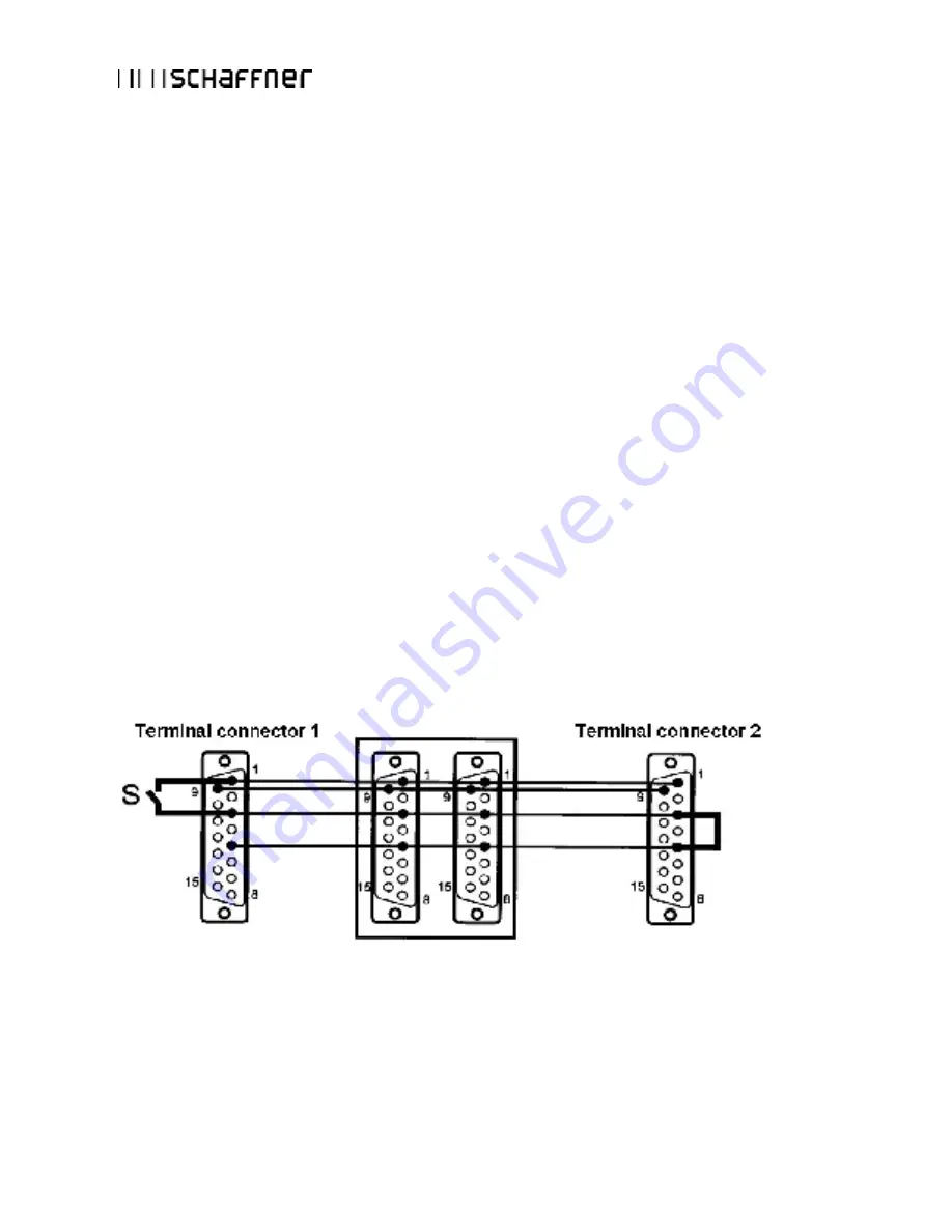
Wiring diagram for the interlock system:
S
: External safety switch (e.g. test enclosure hood, door contact, panic
button, etc...)
Several interlock inputs of this type may be connected in parallel.


