Adjustment_60SMF-LSA 20.05.2021 © Schäfter+Kirchhoff GmbH
Schäfter+Kirchhoff GmbH Kieler Str. 212 22525 Hamburg, Germany +49 40 85 39 97-0 info@sukhamburg.de www.sukhamburg.com
11
If no signal at all is found then the signal area can be increased by slightly loosening the threaded collar of the
FC connector and slightly pulling back the fiber connector. This increases the diameter of the laser spot at the
fiber end-face. Finding the first signal becomes easier. Once a signal is found then gently tighten the collar
and the connector again, remembering to locate the connector key positively against the right-hand side of the
groove in the laser beam coupler, as described in Chapter 2.
7. Tilt Adjustment: Adjustment Procedure, Coarse Adjustment
Once a signal is found, tighten one of the three headed screws (Figure 21), so that the signal is maximized.
Adjust the detector sensitivity as required.
Move on to the next headed screw clockwise (or anti-clockwise) and proceed as described before. After two or
three complete cycles of adjusting all headed screws the last screw is tightened and maximum power at fiber
end is achieved. The adjustment should be now at optimum.
The fine-adjustment to provide the maximum coupling efficiency is done by the locking screws in the next
step.
From now on, the headed adjustment screws are not used anymore.
Notice:
8. Tilt Adjustment: Fine-Adjustment and Locking
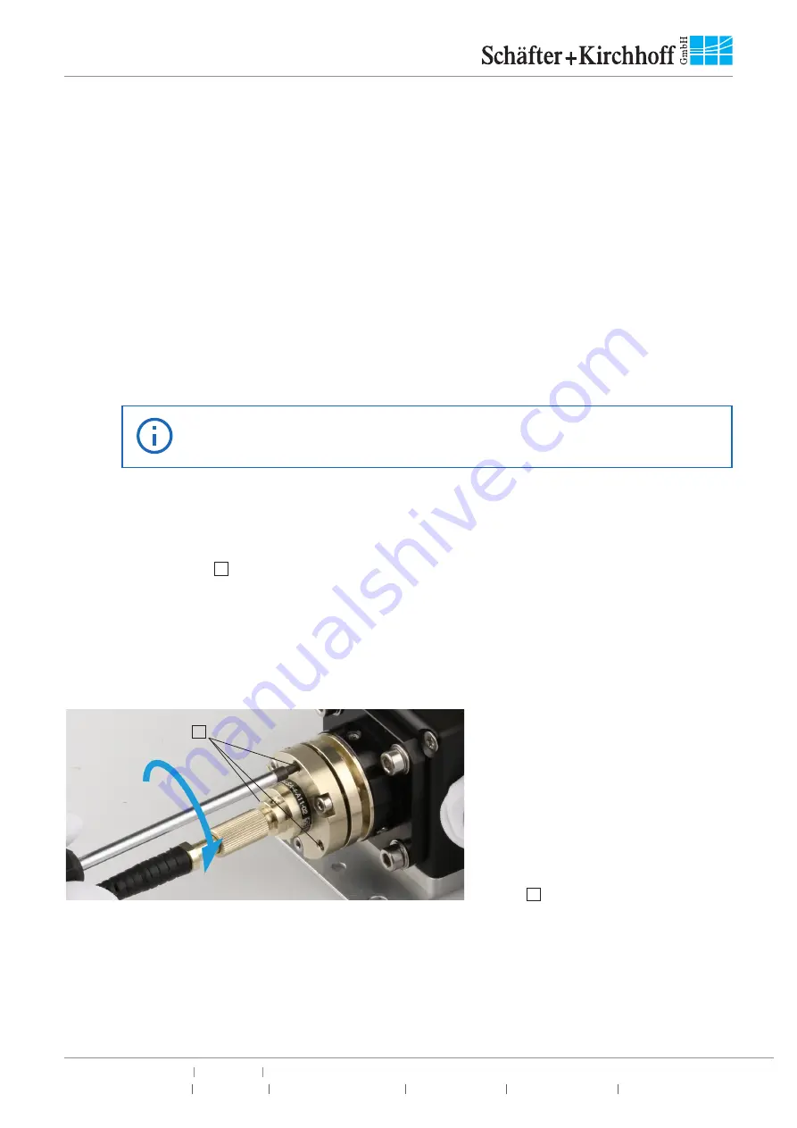
Now, the locking screws are used to fine-adjust and lock the setting. First, fasten the three locking screws
(grub screws, Figure 22,
E
) equally with very gentle force until you feel some resistance. Use the hex key
50HD-15. The detector at the fiber end now shows a signal, but it usually differs from the maximum signal seen
before. The three locking screws are now tightened one after another, e.g. in a clockwise direction. Each screw
is tightened so that the power signal is a little beyond the maximum. The procedures is repeated for each
screw until two are three complete cycles of adjustment are completed. The last screw in the last adjustment
round is tightened in a way, so that the detector shows maximum power at the fiber end. Please note, that the
maximum torque for these screws must not exceed 40 Ncm.
Figure 22:
Fine-adjustment and locking of the
laser beam coupler with the three grub
screws
E
.
9. Checking the Alignment, ‚Thumb Test‘
As a useful check of the optimal alignment, the fiber connector can gently be pressed by hand in different
directions (Figure 23). The coupling efficiency, i.e. the maximum power seen on the detector will change.
However, the induced slight displacement is reversible. Once you stop pressing onto the fiber connector,
the coupling efficiency will be as high as before. When optimally aligned, this slight displacement of the fiber
E


