Adjustment_60SMF-LSA 20.05.2021 © Schäfter+Kirchhoff GmbH
Schäfter+Kirchhoff GmbH Kieler Str. 212 22525 Hamburg, Germany +49 40 85 39 97-0 info@sukhamburg.de www.sukhamburg.com
8
5. Connecting the Laser Beam Coupler to Your System
Before you install the laser beam coupler we recommend to measure the output power of the laser as a
reference for the next steps.
Now, perform the following steps:
Figure 16:
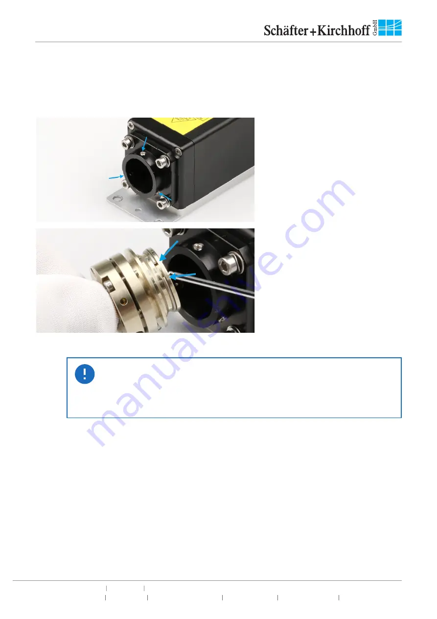
Locate the three radially arranged
tapered pin screws in the adapter
flange (Figure 17) and loosen them
using the hex screwdriver 50HD-15.
Figure 17:
Gently introduce the laser beam
coupler into the vacant aperture. Make
sure that none of the tapered pin
screws are located in the gap.
The
∅
19.5 mm system mount of the 60SMF laser beam coupler has a steel
ring. This steel ring has a gap of approx. 2 mm, see Figure 17. Please make
sure that none of the three pin screw is located in the gap of the steel ring.
Otherwise the connection in between the adapter and the laser beam coupler
and therefore the alignment is not long-term stable.
Attention:
If a polarization-maintaining single-mode fiber is attached to the laser beam coupler, the laser beam coupler
needs to be aligned correctly to the polarization axis of the laser source. In this case, locate the flat part of
the connector receptacle of the laser beam coupler and coarsely rotate the laser beam coupler so that the flat
surface is perpendicular to the polarization axis of the source. (Figure 18).
A fine-adjustment of the polarization axis is performed in a later step, see Chapter 11.


