background image

Laser Beam Couplers Series 60SMS

Adjustment_60SMS    10.12.2020    © Schäfter+Kirchhoff GmbH

Schäfter+Kirchhoff GmbH    Kieler Str. 212    22525 Hamburg, Germany     +49 40 85 39 97-0    info@sukhamburg.de    www.sukhamburg.com

2

Now, make sure that the connector of the fiber you want to attach matches the receptacle type of the laser 
beam coupler:

• 

Use fibers with FC-APC (8°-polish) connectors for laser beam couplers with an inclined coupling 

axis (60SMS-4).

• 

Use fibers with FC-PC (0°-polish) connectors for laser beam couplers with a coaxial axis 

(60SMS-0).

The laser beam couplers are compatible to all fiber connectors type FC, including fiber connectors with end 
caps.

• Do not touch either the optical surface of the lens or the fiber end-face.
• If the coupler is not in use, reattach both rear and front protection caps.

Notice: 

Refer to the laser instruction manual for all instructions regarding laser 
safety!

•   Do not stare directly into the laser beam (which can cause permanent 

damage to the eyes).

•  Do not stare at the reflected beam from reflective objects.
•  Do not point the laser beam to other individuals.

Caution! 

2.  Attaching a Fiber Cable to the Laser Beam Coupler 

For attaching a fiber cable to the laser beam coupler perform the following steps:

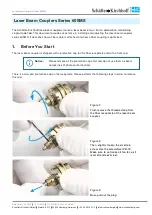
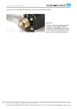
Figure   4: 

To prevent damage to the sensitive 
fiber end-face, always insert the fiber 
connector`s ferrule 

A

 at an angle, with 

the connector key 

B

 properly aligned 

to the receptacle notch 

C

.

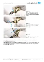
Figure   5: 

When the ferrule tip is safely located 
in the inner cylinder of the receptacle, 
align the connector to the receptac-
le axis and carefully introduce the 
connector into the laser beam coupler.

A

B

C

Summary of Contents for 60SMS Series

Page 1: ...fiber cable is attached and how a fiber coupling is optimized 1 Before You Start The laser beam coupler is shipped with a protection cap for the fiber receptacle and with a front cap Please remove all...

Page 2: ...end face If the coupler is not in use reattach both rear and front protection caps Notice Refer to the laser instruction manual for all instructions regarding laser safety Do not stare directly into...

Page 3: ...onnector cap nut onto the receptacle until it is finger tight Figure 8 Finally gently tighten the fiber grub screw to reduce the free play of the ferrule in the receptacle The free play in between the...

Page 4: ...target about half a Rayleigh length zR away zR 2 beam 2 8 Here is the optical wavelength and beam the collimated beam diameter 1 e2 level Refer to the laser instruction manual for all instructions re...

Page 5: ...burg de www sukhamburg com 5 Figure 10 Insert the eccentric key type 60EX 4 or type 60EX 5 into the large hole Figure 11 Now adjust the focus setting by ro tating the eccentric key Adjust the collimat...

Page 6: ...ers Sch fter Kirchhoff offers an adapter flange which can be moved laterally in oversized holes in order to center the adapter flange to the laser beam Figure 13 Always attach the flange with the reco...

Page 7: ...o sukhamburg de www sukhamburg com 7 Figure 15 Laterally shift the adapter in order to maximize the radiation that is trans mitted by the aperture Only a coarse alignment is necessary which can be don...

Page 8: ...crews are located in the gap The 19 5 mm system mount of the 60SMS laser beam coupler has a steel ring This steel ring has a gap of approx 2 mm see Figure 18 Please make sure that none of the three pi...

Page 9: ...525 Hamburg Germany 49 40 85 39 97 0 info sukhamburg de www sukhamburg com 9 Figure 19 The flat part dashed line has to be perpendicular to the polarization axis of the laser Figure 20 Now fix the thr...

Page 10: ...eyes Do not stare at the reflected beam from reflective objects Do not point the laser beam to other individuals Caution Measure the coupled light at the opposite end of the fiber cable using a light...

Page 11: ...the next step From now on the headed adjustment screws are not used anymore Notice 8 Tilt Adjustment Fine Adjustment and Locking Now the locking screws are used to fine adjust and lock the setting Fi...

Page 12: ...ening the marked locking screw F 10 Focussing the Laser Beam Coupler Focus adjustment adjustment of the coupling lens in z direction is a demanding task and should preferably be performed using a coll...

Page 13: ...tinction ratio The polarization axis of the fiber is adjusted by rotating the laser beam coupler Since both laser beam coupler and fiber are connected this means that the fiber polarization axis is ro...

Page 14: ...g Germany 49 40 85 39 97 0 info sukhamburg de www sukhamburg com 14 analyzer such as the SK010PA Polarization Analyzer from Sch fter Kirchhoff Figure 30 Finally fix the three radially arranged pin scr...

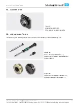
Page 15: ...amburg com 15 13 Accessories Figure 31 Adapter type 60A19 5 F Other adapter types are available 14 Adjustment Tools For assembling and adjusting the laser beam couplers series 60SMS you need the follo...

Page 16: ...an obligation to pay compensation All rights in the event of granting of patents or registration of a utility model Sch fter Kirchhoff GmbH and the Sch fter Kirchhoff logo are registered trademarks T...

Reviews: