Fire-resistant damper model BKA-Ü
Technical documentation
Installation in lightweight partition walls with metal posts
Construction subject to change
No return possible
Version: 2021-07-01 | Page 19
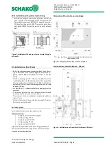
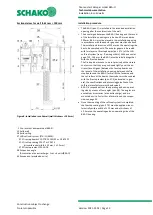
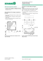
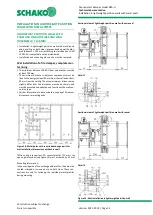
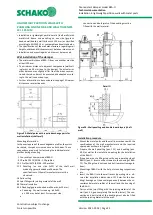
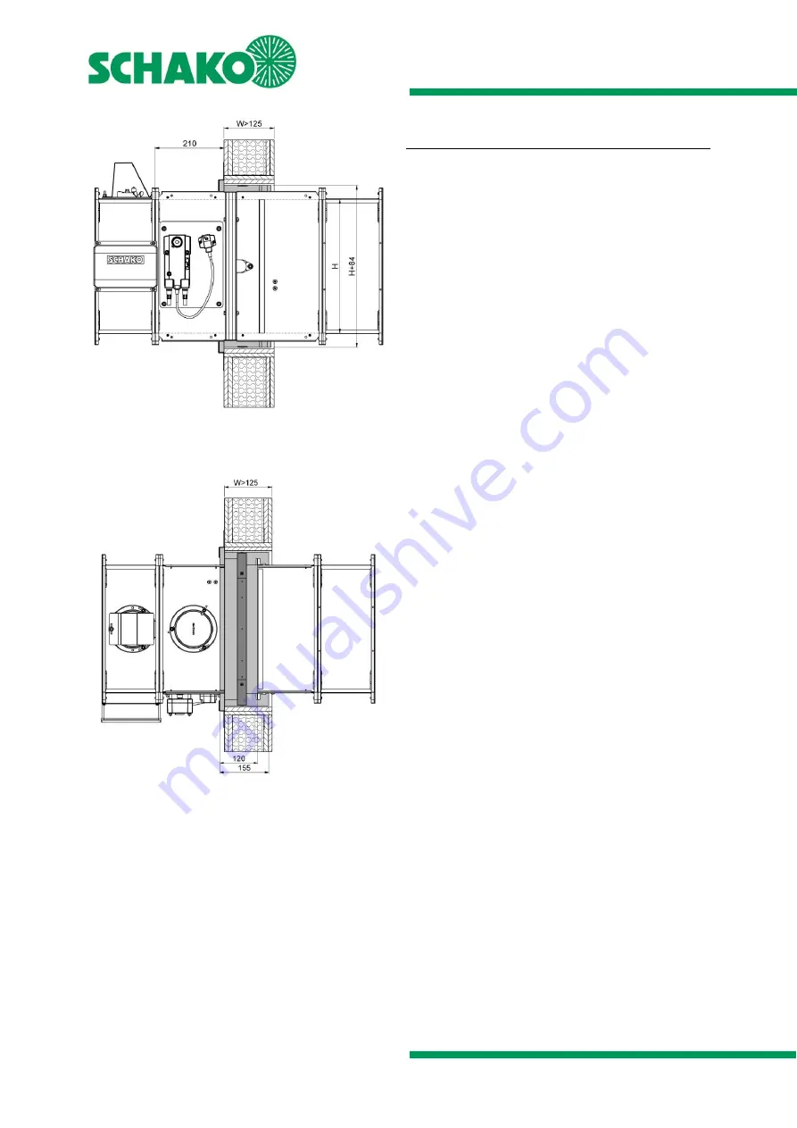
Figure 26: Dry installation in lightweight partition wall (F90)
W > 125, with ER-A1 installation frame
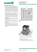
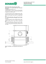
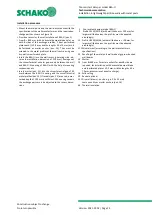
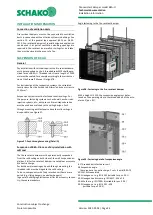
Figure 27: Dry installation in lightweight partition wall (F90)
W > 125, with ER-A1 installation frame
Installation procedure
•
Prepare the metal posts and the wall in accordance with the
specifications of the wall manufacturer and the required ex-
change parts as shown on Figure 18 or Figure 19, page 17.
Leave a recess for installing the BKA-Ü with installation
frame type ER-A1 (pos. 17).
Construct a circumferential reveal (pos. 20) with 12.5 mm
or 2 x 12.5 mm plasterboards and screw them centrally to
the circumferential metal profile frame (pos. 33.2 - fas-
tening: e.g. drywall screws ø 3.5 x 25 mm or ø 3.5 x 45 mm;
screw distance ≤ 250 mm,
but at least 2 screws per side).
Insert the BKA-Ü into the wall recess (dimensions: B+93
+2
mm x H+93
+2
mm), so that the stop of the installation frame
type ER-A1 contacts the wall (operating side
–
observe the
installation dimensions of 210 mm up to the front edge of
the wall, seeFigure 24). Average out the circumferential an-
nular gap evenly between the wall recess and the installa-
tion frame type ER-A1. Mounting of BKA-Ü with the help of
mounting suspensions etc.
BKA-Ü is fastened on all sides to the supporting structure
(exchange profiles
–
pos. 10) using the appropriate number
of fixing lugs (pos. 18; see table 5). The fixing lugs are fas-
tened to the supporting structure using 2 drywall screws
each (pos. 19 e.g. ø 3.5x35 mm; adjust screw length to pan-
elling thickness).
9 Profile CW 50/50/06 (with wall thickness = 100 mm, for
larger wall thicknesses, the profiles must be adapted
accordingly)
10 Profile UW 50/40/06 (with wall thickness = 100 mm, for
larger wall thicknesses, the profiles must be adapted
accordingly)
11.1 Mineral wool (according to the wall manufacturer's
specifications)
12 Panelling (on both sides) of the metal stud wall made of
gypsum-bonded wall boards
16 Solid ceiling
17 ER-A1 installation frame (as accessory at an extra
charge: supplied loose as a mounting kit or factory-
assembled).
17.1 + 17.3 B side Parts 1 and 2
17.2 + 17.4 H side parts 1 and 2
17.5 Countersunk head screw 4.5 x 20 mm
(8 pieces)
17.6 Corner angle ER-A1 (4 pieces)
18 Fixing lugs (included in the scope of delivery of
installation frame type ER-A1)
19 Drywall screws (-on site- 2 x / fixing lug;
e.g. ø 3.5 x 35mm)
20 Circumferential reveal (on site) screwed to metal stud
profiles, depending on the wall thickness (12.5 mm GRP
panels for wall thickness W
≤
125 mm / for W > 125 mm
two layers of reveal (2 x 12.5 mm) are required)
33.2 Drywall screws (-on site- for example, ø 3.5 x 25mm;
screw distance ≤ 250 m
m but at least
2 screws per side)

