Fire-resistant damper model BKA-Ü
Technical documentation
Smoke detection system RMS
Construction subject to change
No return possible
Version: 2021-07-01 | Page 29
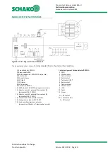
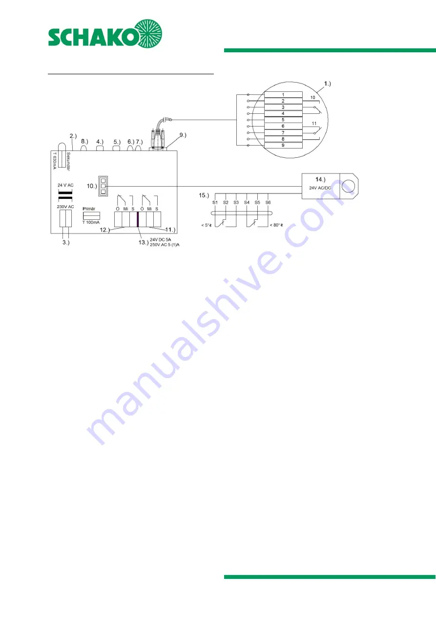
The de-energised state is shown.
For relay module RM, also the alarm or fault condition.
SMOKE DETECTION SYSTEM RMS
Figure 40: Circuit diagram of relay module RM
1.) Smoke detector RMSII-L
2.) Relay module RM
3.) Mains connection - 230V AC 50Hz (on-site)
4.) Reset button
5.) Manual release
6.) LED fault
7.) LED alarm
8.) LED operation
9.) Connection RMSII-L
10.) AMP plug for 24V AC/DC spring return actuator
11.) Selector switch 1; potential-free contact (1)
foot contact (24V / 230V)
12.) Selector switch 2; potential-free contact (2)
foot contact (24V / 230V)
13.) Contact load of the selector switches
14.) Spring return actuator 24V AC/DC
15.) Limit switch spring return actuator
(connection is fitted in a T-piece socket on-site)
Contact assignment Smoke detector RMSII-L:
1 GND
2 Work contact
3 Centre contact
4 Rest contact
5 Test switch / RST
6 Rest contact
7 Centre contact
8 Work contact
9 +24V
10 Fault
11 Alarm
Ö = NC contact
Mi = Centre contact
S = NO contact

