Fire-resistant damper model BKA-Ü
Technical documentation
Installation information
Construction subject to change
No return possible
Version: 2021-07-01 | Page 24
INSTALLATION INFORMATION
Connection of ventilation ducts
Fire-resistant dampers must not be connected to ventilation
ducts in connection with ventilation systems in buildings. See
section 1.2. of the general type approval (aBG) no. Z-6.50-
2012. Fire-resistant dampers of special design and application
can be used if, as part of ventilation planning, openings are
required in fire-resistant inner walls or ceilings for air intake,
they must be closed in the event of a fire.
SUSPENSION OF BKA-Ü
General
Dry installation with soft seal requires the fire-resistant damp-
ers to be suspended on site. 4 threaded rods M10 shall be pro-
vided for each BKA-Ü. Threaded rods from a length of 1500
mm must be coated, for example according to the current ver-
sion of the Promat® Manual, Design 478.
For static design of the suspension systems, the calculated
tensile stress must be limited to 6 N/mm² and shear stress to
10 N/mm².
Suspension systems must be fastened to solid ceilings. For
this purpose, fastening systems such as dowels, anchor rods,
injection systems, etc., with proven fire resistance duration
must be used and matched to the ceiling designs. Push-
through mounting with fasteners above the solid ceilings is
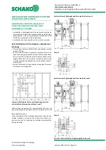
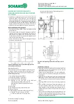
also possible, see Figure 37.
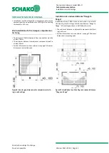
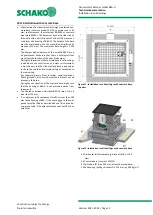
Figure 37: Push-through mounting (Detail A)
Suspension of BKA-Ü in case of dry installation with
soft seal
The fire resistant damper must be permanently suspended
from the solid ceiling on both sides of the wall. Suspension an-
gle (pos. 38) for fire-resistant damper is available as accessory
at an extra charge.
For both dowel mounting and push-through mounting, the
threaded rods must be hinged to the solid ceiling.
To do so, components with fire protection certificate are re-
quired (e.g. sliding hangers, pendulum hangers).
In general, building regulations can differ from country to coun-
try; these are mandatory.
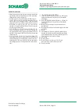
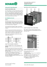
Angle fastening to the fire-resistant damper
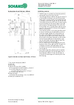
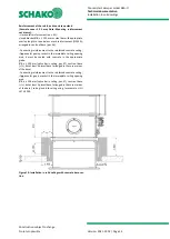
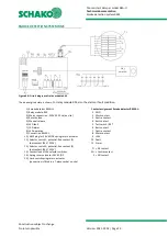
Figure 38: Fastening to the fire-resistant damper
With a height H ≤ 250, the suspension angle must be fas-
tened on the operating side to the threaded bolt of the actu-
ator unit (pos. 8.1).
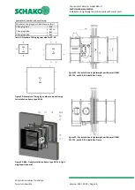
Figure 39: Fastening detail of suspension angle
8.1 Threaded bolt of actuator unit
38 Suspension angle
(Accessories at an extra charge: 1 set = 4 units/BKA-Ü)
39.1 M10 threaded rod
39.2 Hexagon nut e.g. ISO 4032 (suitable for pos. 39.1)
39.3 Hexagon head screw e.g. ISO 4017 - M6 x 20
39.4 Washer e.g. ISO 7090
–
6 (suitable for pos. 39.3)
39.5 Hexagon nut e.g. ISO 4032
–
M6
(suitable for pos. 39.3)

