Fire-resistant damper model BKA-Ü
Technical documentation
Add-on parts
Construction subject to change
No return possible
Version: 2021-07-01 | Page 30
ADD-ON PARTS
Installation frame type ER-A1
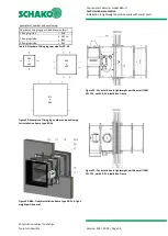
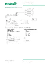
Figure 41: BKA-Ü with ER-A1 installation frame (loose)
1 Fire-resistant damper model BKA-Ü
17 Installation frame type ER-A1 (accessory, at an extra
charge).
17.1 H side part 1
17.2 B side part 1
17.3 H side part 2
17.4 B side part 2
17.5 Countersunk head screw 4.5 x 20 mm (8 pieces)
17.6 Corner angle ER-A1 (4 pieces)
18 Fixing lugs (not shown; included in the scope of delivery
of installation frame type ER-A1)
Installation frame type ER-A1 consisting of silicate boards,
incl. fastening material, with a circumferential intumescent
seal located in its centre.
Intended use:
For installation of the BKA-Ü in lightweight partition walls
with metal posts and panelling on both sides according to
classification to EN 13501-2 or comparable national stand-
ards.
The ER-A1 installation frame is to be ordered as an accessory
(extra charge)
–
supplied loose or factory-mounted. If the in-
stallation frame type ER-A1 is already mounted ex works to
the BKA-Ü, the installation in the wall can immediately take
place.
If the ER-A1 installation frame has been ordered or delivered
loose as a mounting kit, it must be mounted to the BKA-Ü (see
Figure 41) following the instructions described below.
To avoid damage to the components when mounting the in-
stallation frame ER-A1, BKA-Ü must be placed on a suitable
surface (e.g. cardboard, pallet etc.) during mounting.
All holes required for screw mounting have been predrilled ex
works on the installation frame type ER-A1, no further holes
must be drilled. The installation frame ER-A1 may not be
screw-connected directly to the housing of BKA-Ü.
Mounting procedure
Place the BKA-Ü on the flange of the operator side (BS).
The two B side and H side parts (pos. 17.1 - 17.4) are posi-
tioned around the BKA-Ü housing (pos. 1), as shown in Figure
41.
They are then screwed together with the supplied corner
angles (pos. 17.6) and the corresponding countersunk
screws (pos. 17.5) in the corner area.
Mortar anchor
Perforated plate t ≥ 0.5 mm; width x
length = 40 x 70 mm
(accessories at an extra charge: 1 set = 40 pieces). From a
width > 800 mm (with horizontal damper blade axle) (article
3231690).
Intended use: In case of wet installation in lightweight par-
tition walls with metal posts and panelling on both sides ac-
cording to classification to EN 13501-2 or comparable na-
tional standards.
Suspension angle
4 pieces (= 1 set, at an extra charge) per BKA-Ü damper are
required. Select the angle material (SV; V2A; V4A) according
to the housing material of the BKA-Ü.
SV = article 5007240;
V2A = article 5007242;
V4A = article 5007241;
Intended use: For installation with Hilti soft seal system.
Legend
V
zu
[m³/h] [l/s] = Supply air volume
p
[Pa]
= Static pressure difference
L
WA
dB(A)
= A-weighted sound power level
V
stirn
[m/s]
= Face velocity
[kg/m
3
]
= Density
B
[mm]
= Width
H
[mm]
= Height
min.
= at least
or
= or
approx.
= approximately


