Fire damper BKP-EN
Technical documentation
Installation in solid ceilings
Construction subject to change.
No return possible!
Version: 2020-09-01 | Page 11
Wet installation with concrete base
•
Construction of a circumferential, straight reinforced con-
crete base (concrete grade: C20/25; concrete cover ≥ 35
mm; reinforcement: concrete steel BSt500S concrete
steel mats B500A). The base must be constructed circum-
ferentially with a wall thickness of at least 100 mm, meas-
ured from the housing of the fire damper. The height of
the base must be maintained up to the prescribed instal-
lation dimension (200 mm). The maximum base height is
≤ 550 mm.
The damper leaf clearance of the installed fire damper
must be guaranteed. Make sure that there is nothing left
that may affect the function of the new fire damper.
Prior to installation of the fire damper, fastening materials
(e.g. screws, press-in nuts, etc.) must be provided and at-
tached on the non-operating side for mounting duct com-
ponents or, if subsequent mounting is no longer possible,
the ventilation duct must be connected prior to installa-
tion. Alternatively, extension pieces (on site or as acces-
sories, e.g. SCHAKO type VT) can be mounted.
During the formation of the concrete base on solid ceil-
ings, in addition to the constructive anti-crack reinforce-
ment, it must be ensured that the concrete base is applied
directly to the reinforced concrete ceiling or connected to
the raw ceiling.
Any separating layers (floor coverings, seals, insulations,
floating screeds, etc.) must be removed or must not be
present in this area.
During the construction of the concrete base, make sure
that the housing of the fire damper is not pressed inwards
(reinforcement).
•
The minimum distance of fire dampers from one another
must be at least 200 mm.
•
If an adjacent solid component (wall) is closer than 100
mm to the housing of fire damper, the existing gap to this
component must be filled as described above. This option
becomes available if the adjacent component has F90
characteristics.
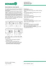
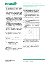
Figure 10: Installation in solid ceilings with concrete base,
top view
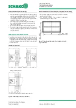
Figure 11: Installation in solid ceilings with concrete base
16 Solid ceiling
34 Horizontal reinforcement e.g. bracket (Ø 8; e ≤ 150 mm)
35 Concrete base (concrete C20/25)
36 Splice bars (Ø 8; e ≤ 500 mm; at least 4 pieces/base)
Reinforcement of the reinforced concrete upstand
(Concrete cover ≥ 35 mm; Note: Mounting reinforcement
not drawn):
- Horizontal reinforcement (pos. 34):
closed bracket Ø 8, e ≤ 150 mm or steel bar with appropriate
overlap lengths or equivalent mesh reinforcement (Q335A);
arranged in centre of base (pos. 35).
- Connecting reinforcement to the reinforced concrete ceiling,
if
an
annular gap is present in the immediate ceiling opening
area, it must be sealed with concrete in the appropriate
grade:
Ø 8 e ≤ 500 mm (splice bar in ceiling, pos. 36) centre of base
(=/=), but at least 4 pieces/base (arranged in the corner areas
of the base)
- Connecting reinforcement to the reinforced concrete ceiling,
if
no
annular gap is present in the immediate ceiling opening
area.
Ø 8 e ≤ 500 mm (splice bar in ceiling, pos. 36) centre of base
(=/=), but at least 4 pieces/base (arranged in the corner areas
of the base); to be glued into ceiling using, for example, Hilti
HIT HY 200.
Figure 12: Installation in solid ceilings with concrete base,
section

